
Special high-efficiency curing device for injection molding panel preparation

A curing equipment and high-efficiency technology, which is applied in the direction of pretreatment surface, device for coating liquid on the surface, coating, etc., can solve the problems of heat loss, low drying efficiency, uneven drying, etc., and reduce heat loss , improve the curing quality, solve the effect of uneven drying

Active Publication Date: 2020-11-03
丹阳市逸帆电子有限公司
View PDF8 Cites 0 Cited by
  • Summary
  • Abstract
  • Description
  • Claims
  • Application Information

AI Technical Summary

Problems solved by technology

[0003]The drying effect of the existing assembly line injection molding panel curing equipment is not good, and the drying efficiency is low. Since the drying device is directly installed on the conveyor belt, the drying equipment only It can dry the surface of the injection molding panel, but the edge part cannot be dried effectively, resulting in uneven drying, and there is a direct distance between the drying equipment and the conveyor belt, resulting in heat loss, which further affects the drying effect
Due to the poor airtight effect of the existing UV curing equipment on the assembly line, it is easy to cause ultraviolet rays to leak out, which will cause harm to the staff, and the position of the ultraviolet lamp in the curing equipment is fixed, so that the light source cannot evenly cover the edge of the injection molding panel , thus affecting the UV curing effect

Method used


Image

  • Special high-efficiency curing device for injection molding panel preparation
  • Special high-efficiency curing device for injection molding panel preparation
  • Special high-efficiency curing device for injection molding panel preparation

Examples


Embodiment Construction

[0028] In order to make the technical solution of the present invention clearer, the present invention will be further described below in conjunction with the accompanying drawings. Any solution obtained by equivalent replacement and conventional reasoning of the technical features of the technical solution of the present invention falls within the protection scope of the present invention. The fixed connection mentioned in the present invention and the fixed arrangement are common connection methods in the mechanical field, and welding, bolt and nut connection and screw connection are all available.

[0029] In describing the present invention, it is to be understood that the terms "upper", "lower", "front", "rear", "left", "right", "vertical", "horizontal", "top" , "bottom", "inner", "outer" and other indicated orientations or positional relationships are based on the orientations or positional relationships shown in the drawings, and are only for the convenience of describin...


PUM


Abstract

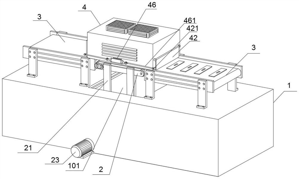
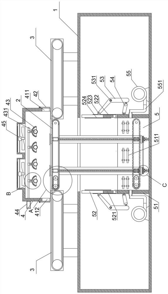
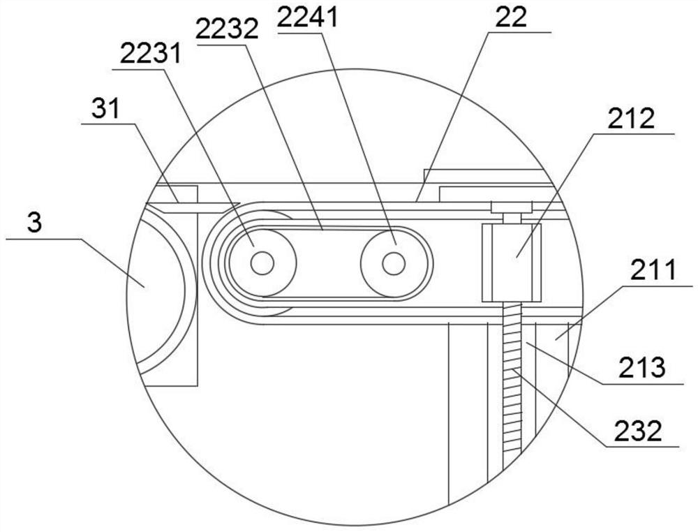
The invention relates to a special high-efficiency curing device for injection molding panel preparation. The special high-efficiency curing device comprises a machine base, wherein a lifting openingwith a rectangular structure is formed in the upper surface of the machine base, a lifting conveying mechanism is arranged at the lifting opening, two fixed conveying mechanisms are arranged at the positions, located at the two ends of the lifting opening, on the machine base, the two fixed conveying mechanisms are located at the two ends of the lifting conveying mechanism correspondingly, and convey injection molding panels to the lifting conveying mechanism, a curing device body is arranged above the lifting conveying mechanism, the bottom end of the curing device body is fixedly arranged atthe tops of the lifting conveying mechanism and the two fixed conveying mechanisms, the curing device body is used for carrying out UV curing treatment on the injection molding panels on the liftingconveying mechanism, a drying device is arranged below the lifting conveying mechanism, the drying device is arranged at the bottom end in the machine base, and the drying device is used for carryingout thermocuring treatment on the injection molding panels on the lifting conveying mechanism. The occupied space of the curing device is saved, the drying device can effectively reduce heat loss during heating, and the problem of uneven drying is effectively solved.

Description

technical field [0001] The invention belongs to the technical field of injection molded parts production equipment, and in particular relates to a special high-efficiency curing equipment for injection molding panel preparation. Background technique [0002] At present, when the injection molded parts are prepared, they need to be sprayed with hardened paint, that is, a layer of hardened paint layer structure is sprayed on the surface of the injection molded parts, and the curing method of the paint layer in the production process of the injection molding panel includes two steps of heat curing and ultraviolet light curing. , thermal curing adopts the drying method to dry the paint on the surface of the injection molding panel. UV curing means that after the paint absorbs the high-temperature ultraviolet light in the ultraviolet light curing equipment, it instantly generates active free radicals or ion radicals, and then produces The polymerization reaction makes the UV coat...

Claims


Application Information

Patent Timeline
Patent Type & Authority Applications(China)
IPC IPC(8): B05D3/02B05D3/06B05D3/04
CPCB05D3/0254B05D3/067B05D3/0413Y02P70/10
Inventor 黄耀平
Owner 丹阳市逸帆电子有限公司
Learn More