
Grinding device with protective structure for alloy saw blade processing

A protective structure and saw blade technology, which is applied in the direction of grinding drive devices, metal processing equipment, grinding/polishing safety devices, etc., can solve the problems of low efficiency of grinding speed, sputtering of tooth grooves, and harm to human body, etc. Effects of work load, reduction of energy consumption, and prevention of sputtering of debris

Active Publication Date: 2021-06-29
浙江特佳利工具有限公司
View PDF0 Cites 0 Cited by
  • Summary
  • Abstract
  • Description
  • Claims
  • Application Information

AI Technical Summary

Problems solved by technology

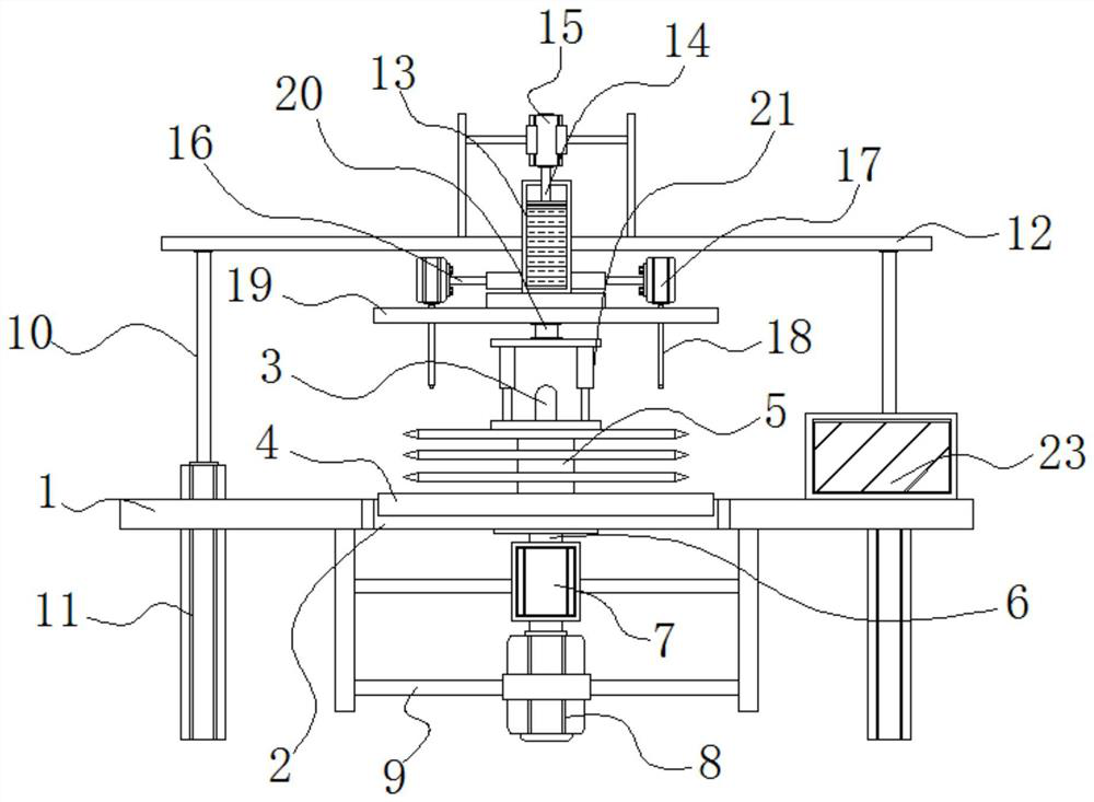
[0004] Aiming at the deficiencies of the prior art, the present invention provides a grinding device with a protective structure for processing alloy saw blades, which solves the problem that the existing grinding device proposed in the above background technology can only perform single-piece single-tooth grinding on alloy saw blades. The grinding speed is inefficient, and the grinding device needs to be manually pre-adjusted according to the size of the alloy sawtooth before operation. Manual debugging is very prone to errors, resulting in sputtering of the alveoli, which is harmful to the human body.

Method used


Image

  • Grinding device with protective structure for alloy saw blade processing
  • Grinding device with protective structure for alloy saw blade processing
  • Grinding device with protective structure for alloy saw blade processing

Examples


Embodiment Construction

[0025] The following will clearly and completely describe the technical solutions in the embodiments of the present invention with reference to the accompanying drawings in the embodiments of the present invention. Obviously, the described embodiments are only some, not all, embodiments of the present invention.

[0026] In the description of the present invention, unless otherwise stated, the meaning of "plurality" is two or more; the terms "upper", "lower", "left", "right", "inner", "outer" , "front end", "rear end", "head", "tail", etc. indicate the orientation or positional relationship based on the orientation or positional relationship shown in the drawings, and are only for the convenience of describing the present invention and simplifying the description, rather than Nothing indicating or implying that a referenced device or element must have a particular orientation, be constructed, and operate in a particular orientation should therefore not be construed as limiting ...


PUM


Abstract

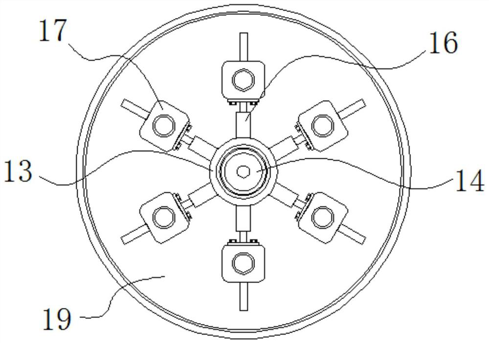
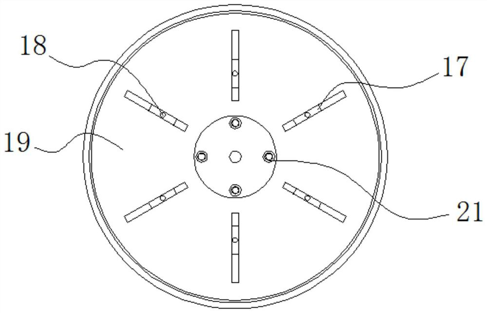
The invention discloses a grinding device with a protective structure for processing alloy saw blades, relates to the technical field of grinding devices, and specifically relates to a grinding platform and a saw blade grinding mechanism. The bottom of the surface is sleeved with a waste collection tray, the bottom of the lifting plate is connected to a rotating shaft, the bottom of the gearbox is connected to a rotating motor, the saw blade grinding mechanism is arranged on both sides of the grinding platform, and the middle of the plate frame is embedded with a A hydraulic cylinder, the bottom of the bearing is connected with a spring telescopic rod, and a touch control screen is arranged at the right corner of the grinding platform. The alloy saw blade is processed with a grinding device with a protective structure. The alloy saw blades of the same size to be polished are socketed on the surface of the placement column, and the two are separated in parallel by a partition, and then enter the overlapping position through the rotating grinding cylinder. Grinding in the tooth groove, this setting is conducive to the grinding operation of multiple saw blades and multiple tooth grooves at the same time, which is conducive to improving work efficiency.

Description

technical field [0001] The invention relates to the technical field of grinding devices, in particular to a grinding device with a protective structure for processing alloy saw blades. Background technique [0002] The alloy saw blade is the most core part of the cutting device. The object can be cut by driving the alloy saw blade to rotate at high speed through the motor. However, the friction between the alloy saw blade and the object will lead to the passivation of the tooth groove, so it is necessary to Regularly sharpen the alloy saw blade to maintain its sharpness. [0003] The existing grinding device can only grind a single piece and a single tooth of the alloy saw blade, which makes the grinding speed inefficient, and the grinding device needs to manually perform various pre-adjustments according to the size of the alloy saw teeth before operation, and manual debugging is prone to errors Cause alveolar cracking and sputtering, thus endangering the human body. Con...

Claims


Application Information

Patent Timeline
Patent Type & Authority Patents(China)
IPC IPC(8): B24B3/58B24B27/00B24B41/06B24B47/00B24B47/12B24B47/20B24B55/06B24B55/12
CPCB24B3/586B24B27/0023B24B27/0076B24B41/061B24B47/00B24B47/12B24B47/20B24B55/06B24B55/12
Inventor 徐伟家
Owner 浙江特佳利工具有限公司
Learn More