Drilling fluid sand pump for oil exploitation and using method thereof

A technology for oil extraction and drilling fluid, applied in the direction of pumps, pump devices, pump components, etc., can solve the problems of increasing the load of bearings and seals, uneven force of the main shaft 7, speeding up bearing loss, etc., so as to reduce the bearing load and improve the operation. Efficiency, the effect of reducing the probability of failure

Inactive Publication Date: 2020-11-03
广州市顺创科技有限公司
View PDF6 Cites 2 Cited by
  • Summary
  • Abstract
  • Description
  • Claims
  • Application Information

AI Technical Summary

Problems solved by technology

[0003] More than 85% of the sand pumps used on the drilling site are horizontal sand pumps, and more than 90% of the failures of horizontal sand pumps are caused by seals. Usually, the seals of sand pumps are mainly divided into two types. Fill the box with soft stuffing, and apply a certain pressure to make the stuffing fill the stuffing box, so as to achieve the sealing effect. The second is a mechanical seal device composed of a pair or several pairs of friction pairs composed of a moving ring and a static ring. It is Depending on the pressure of the elastic element and the sealing medium, an appropriate pressing force is generated on the end faces of the rotating dynamic and static rings, so that they fit closely, so as to maintain a very thin liquid film to achieve the purpose of sealing, but both of them are in use. The same problem exists. When the speed of the impeller 5 increases and the pressure inside the volute gradually increases, the drilling fluid easily penetrates into the stuffing box or the sealing surface of the mechanical seal device, and the drilling fluid containing mud and sand enters the stuffing box, causing shaft The casing is severely worn, and once the sandy drilling fluid enters the sealing surface of the mechanical seal, the sealing pair will wear quickly and fail completely
[0004] At present, the structure of the centrifugal sand pump is the cantilever support of the impeller, that is, the structure of the outrigger beam is T-shaped. When the impeller 5 rotates in this structure, because the wear-resistant plate is corroded by the drilling fluid and the wear is uneven, The force generated by the rotation of the main shaft 7 is uneven, resulting in fine vibration, and increases the load on the bearing and seal, and has a large deflection, which accelerates the loss of the bearing, makes the seal invalid, and causes leakage

Method used


Image

  • Drilling fluid sand pump for oil exploitation and using method thereof
  • Drilling fluid sand pump for oil exploitation and using method thereof
  • Drilling fluid sand pump for oil exploitation and using method thereof

Examples


Embodiment Construction

[0025] The following will clearly and completely describe the technical solutions in the embodiments of the present invention with reference to the accompanying drawings in the embodiments of the present invention. Obviously, the described embodiments are only some, not all, embodiments of the present invention. Based on the embodiments of the present invention, all other embodiments obtained by persons of ordinary skill in the art without making creative efforts belong to the protection scope of the present invention.

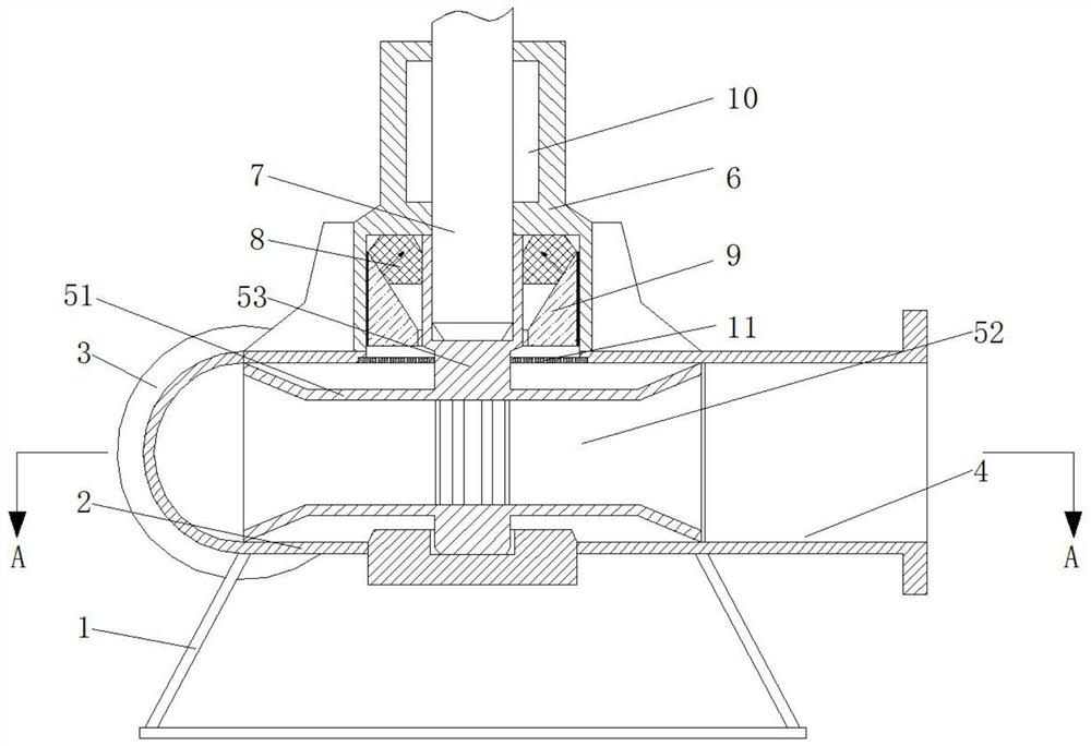
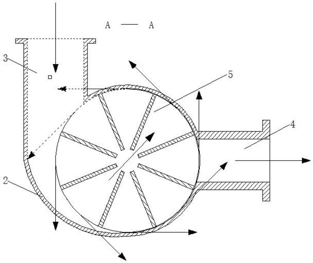
[0026] see Figure 1-5 , a drilling fluid sand pump for oil production, comprising an underframe 1, a sealing assembly 10 and an external motor, the top of the underframe 1 is fixedly equipped with a movable chamber 2, and the left side of the back of the movable chamber 2 is provided with a low-pressure inlet 3, and the movable chamber 2 There is a high-pressure outlet 4 in the middle part of the right side of the motor, the middle part of the inner cavity of...


PUM


Abstract

The invention relates to the technical field of oil exploitation, and discloses a drilling fluid sand pump for oil exploitation. The drilling fluid sand pump comprises a bottom frame, a sealing assembly and an external motor, wherein a movable cavity is fixedly formed in the top of the bottom frame, a low-pressure inlet is formed in the left side of the back of the movable cavity, a high-pressureoutlet is formed in the middle of the right side of the movable cavity, an impeller is movably connected to the middle of an inner cavity of the movable cavity in a sleeved mode, and a fixing frame isfixedly installed on the top surface of the movable cavity. Through the arrangement of a wear-resisting rubber ring and a extrusion block, when the rotating speed of the impeller is increased to enable the pressure inside the movable cavity to be increased, the extrusion block is extruded upwards to increase the contact force between the wear-resisting rubber ring and the extrusion block and between the wear-resisting rubber ring and a main shaft, so that the sealing performance inside the movable cavity is reinforced along with the increase of the rotating speed and the pressure, and the failure probability caused by leakage of a sand pump is reduced; and moreover, a layer of protection is provided for the sealing assembly, invasion of a drilling fluid is reduced, the service life of thesealing assembly is prolonged, and the maintenance cost is reduced.

Description

technical field [0001] The invention relates to the technical field of oil extraction, in particular to an oil extraction drilling fluid sand pump and a method for using the same. Background technique [0002] The sand pump is one of the important equipment in the drilling fluid solid phase control system. Its main function is to provide drilling fluid with a certain pressure and displacement for the drilling fluid sand removal, desilter and swirl mixer. At present, the drilling site The sand pumps used are large-displacement centrifugal pumps. Centrifugal pumps are divided into horizontal and vertical centrifugal pumps. The working principle of horizontal centrifugal pumps is as follows. Figure 6 As shown, the drilling fluid enters the impeller 5 vertically from the low-pressure inlet 3, and the external motor drives the main shaft 7 to rotate, thereby driving the impeller 5 to rotate, generating centrifugal force, and discharging the drilling fluid in the impeller 5 from t...

Claims


Application Information

Patent Timeline
Patent Type & Authority Applications(China)
IPC IPC(8): F04D1/00F04D7/04F04D13/06F04D29/10F04D29/22
CPCF04D1/00F04D7/04F04D13/06F04D29/106F04D29/22
Inventor 郑波
Owner 广州市顺创科技有限公司
Why Eureka
Try Eureka