
High and low frequency composite structure base station antenna loaded with artificial magnetic conductor structure reflecting plate

An artificial magnetic conductor and composite structure technology, applied in the field of mobile communications, can solve the problems of increasing the lateral size of the antenna radiator, low isolation, asymmetrical pattern, etc., and achieve the effect of alleviating the shortage of sky resources and low profile height

Active Publication Date: 2020-11-03
CHONGQING UNIV OF POSTS & TELECOMM
View PDF9 Cites 4 Cited by
  • Summary
  • Abstract
  • Description
  • Claims
  • Application Information

AI Technical Summary

Problems solved by technology

[0005] However, the existing technology has the following disadvantages: the existing base station antenna uses loading resonators or parasitic branches to introduce new resonance modes to broaden the frequency band, which will cause problems with the bandwidth of the pattern; the "side by side" arrangement of high and low frequency units and coaxial Nesting will cause problems such as high and low frequency mutual coupling, resulting in low isolation and asymmetrical pattern; loading short-circuit walls or short-circuit probes will reduce the efficiency and gain characteristics of the antenna; increasing the dielectric constant of the dielectric substrate can usually also increase the dielectric constant at the resonant frequency. Reduce the size of the antenna without changing the size, but too large a dielectric constant will consume a lot of energy, resulting in problems such as low gain of the antenna and time-domain waveform distortion of the transmitted signal; the miniaturization of the antenna is realized by meandering technology It will increase the lateral dimension of the radiator part of the antenna, and the asymmetry of the radiator structure will also lead to excessive cross polarization, which will cause the antenna's directivity to deteriorate

Method used


Image

  • High and low frequency composite structure base station antenna loaded with artificial magnetic conductor structure reflecting plate
  • High and low frequency composite structure base station antenna loaded with artificial magnetic conductor structure reflecting plate
  • High and low frequency composite structure base station antenna loaded with artificial magnetic conductor structure reflecting plate

Examples


Embodiment Construction

[0045]Embodiments of the present invention are described below through specific examples, and those skilled in the art can easily understand other advantages and effects of the present invention from the content disclosed in this specification. The present invention can also be implemented or applied through other different specific implementation modes, and various modifications or changes can be made to the details in this specification based on different viewpoints and applications without departing from the spirit of the present invention. It should be noted that the diagrams provided in the following embodiments are only schematically illustrating the basic concept of the present invention, and the following embodiments and the features in the embodiments can be combined with each other in the case of no conflict.

[0046] Wherein, the accompanying drawings are for illustrative purposes only, and represent only schematic diagrams, rather than physical drawings, and should ...


PUM


Abstract

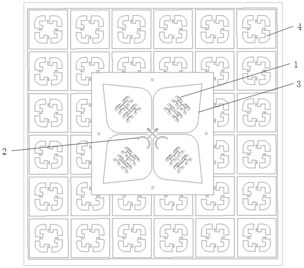
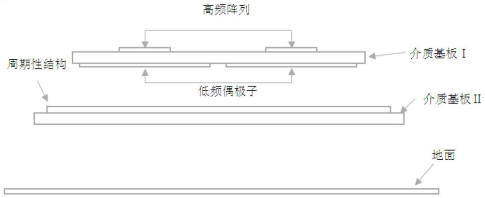
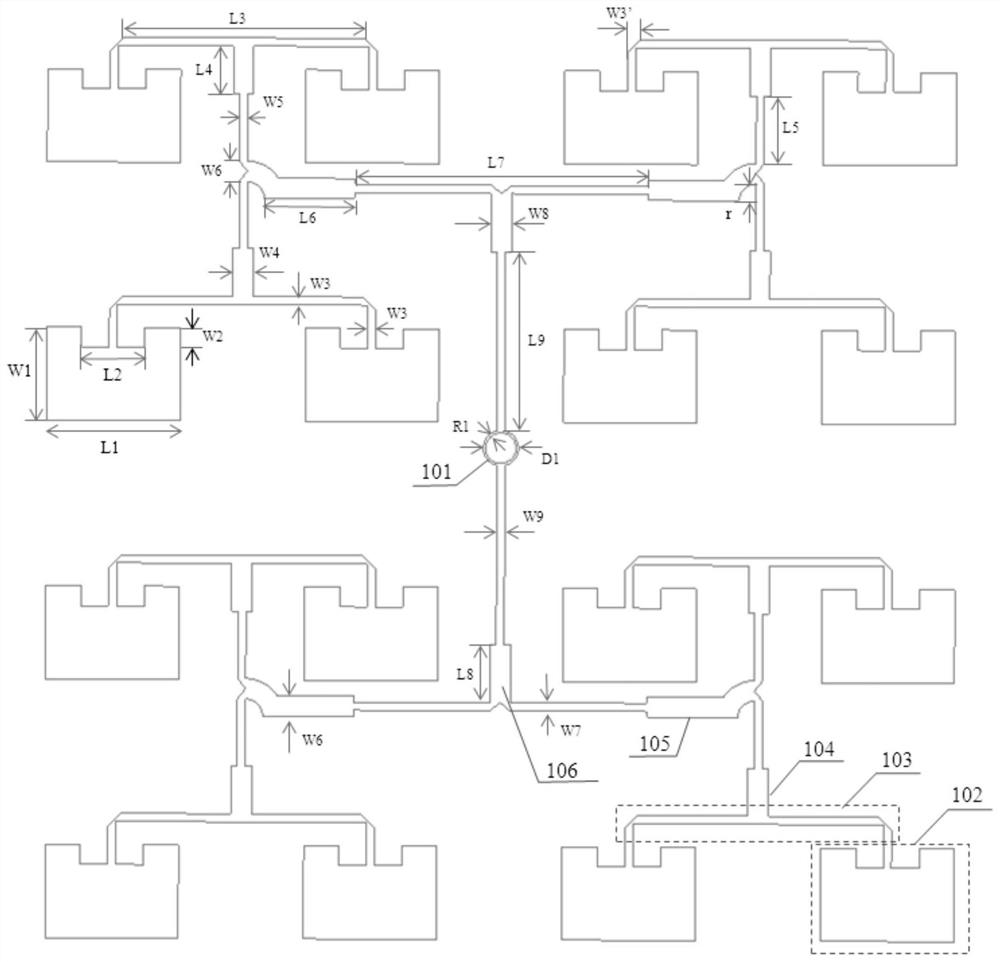
The invention relates to a high and low frequency composite structure base station antenna loaded with an artificial magnetic conductor structure reflecting plate, and belongs to the field of wirelesscommunication. The antenna comprises a high-frequency antenna unit, a low-frequency antenna unit, a first dielectric substrate and a reflecting plate, the high-frequency antenna unit is composed of four pairwise orthogonal 4 * 4 rectangular microstrip array antennas. The low-frequency antenna unit is composed of two pairs of leaf-shaped dipole patches, two crossed and orthogonal crescent microstrip feeder lines and a rectangular feeder line bridge. The low-frequency antenna unit is coupled with the dipole patch through two orthogonal crescent microstrip feeders for feeding; the metasurface structure in the reflecting plate is formed by periodically arranging metal patches on a second dielectric substrate; the periodic structure is a rectangular patch array formed by etching four '5'-shaped gaps on a rectangular metal patch in a 6 * 6 manner. The base station antenna is simple in feeding mode, easy to realize, low in profile height and multi-frequency, and can realize 5G / 4G / 3G multi-system coverage.

Description

technical field [0001] The invention belongs to the technical field of mobile communication, and relates to a base station antenna with a high-low frequency composite structure loaded with an artificial magnetic conductor structure reflector. Background technique [0002] With the rapid development of mobile communication systems, multiple communication standards exist in cellular wireless networks. Under the circumstances that 5G (fifth generation mobile communication system) has been commercialized but is still immature and 4G is still the main communication standard, co-site coexistence of multi-standard systems has become a problem that must be solved in the future. At the same time, the base station antenna resources of the current mobile communication system are scarce, and many base stations in many residential areas have also led to residents who are afraid of electromagnetic radiation rejecting the construction of new base station antennas. Therefore, the current d...

Claims


Application Information

Patent Timeline
IPC IPC(8): H01Q1/24H01Q1/36H01Q1/50H01Q1/52H01Q5/28H01Q15/00H01Q15/14H01Q21/28
CPCH01Q1/246H01Q1/36H01Q1/50H01Q21/28H01Q15/0086H01Q15/14H01Q5/28H01Q1/523
Inventor 罗伟倪志雄郝宏刚尹波杨钰琦
Owner CHONGQING UNIV OF POSTS & TELECOMM
Learn More