Eureka AIR delivers breakthrough ideas for toughest innovation challenges, trusted by R&D personnel around the world.

Full-automatic vacuum tight coupling gas atomization device and method thereof

A fully automated, tightly coupled technology, applied in the field of vacuum air atomization to prepare metal powder, can solve the problems of low sensitivity, affecting the industrial production process of VIGA technology, poor stability, etc., to reduce costs, prevent nodules and blockage, prevent The effect of molten steel leakage

Active Publication Date: 2020-11-06
ZHONGTIAN SHANGCAI ADDITIVE MFG CO LTD
View PDF9 Cites 3 Cited by
  • Summary
  • Abstract
  • Description
  • Claims
  • Application Information

AI Technical Summary

Problems solved by technology

Due to the need for operators to pay attention to many details when pouring steel atomization, and the traditional hydraulic control method has poor stability and low sensitivity, this puts forward higher requirements for operators, which seriously affects the industrialization of VIGA technology Production Process

Method used


Image

  • Full-automatic vacuum tight coupling gas atomization device and method thereof
  • Full-automatic vacuum tight coupling gas atomization device and method thereof
  • Full-automatic vacuum tight coupling gas atomization device and method thereof

Examples


Embodiment 1

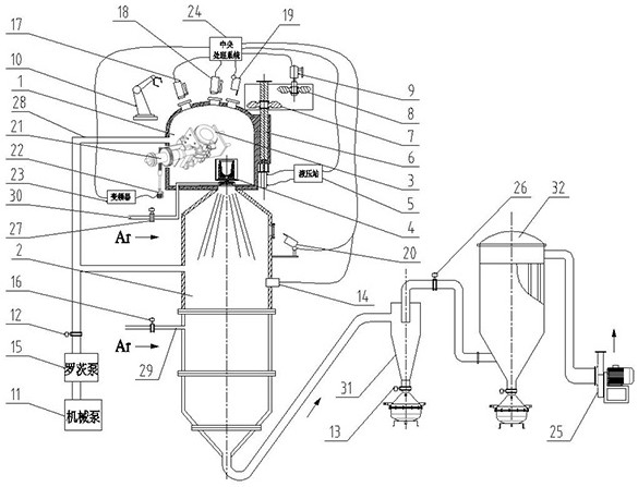
[0052] Taking the preparation of 316L stainless steel metal powder for 3D printing as an example, a fully automatic gas atomization method of a vacuum close-coupled gas atomization device of the present invention includes the following steps:

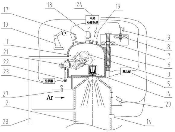
[0053] (1) Loading: The central processing system 24 issues a "loading" command, and the hydraulic station 5 drives the hydraulic cylinder 6 to drive the furnace cover of the smelting chamber 1 up until the first gear 7 meshes with the second gear 7; then the first motor 9 drives the second gear 7 to rotate, and drives the furnace cover of the smelting chamber 1 to rotate 90° and then stops, and then the feeding manipulator 10 starts to move the 316L rods into the crucible 3; when the charge reaches 220kg, the first motor 9 reverses Turn 90° to return to the initial position, then the hydraulic station 5 drives the hydraulic cylinder 6, and drives the furnace cover of the smelting chamber 1 down until the furnace cover is closed, realizi...

Embodiment 2

[0061] Taking the preparation of 18Ni300 stainless steel metal powder for 3D printing as an example, a fully automatic gas atomization method of a vacuum close-coupled gas atomization device of the present invention includes the following steps:

[0062] (1) Loading: The central processing system 24 issues a "loading" command, the hydraulic station 5 drives the hydraulic cylinder 6, and drives the furnace cover of the melting chamber 1 to rise until the first gear 7 meshes with the second gear 8; then the first motor 9 drives the second gear 8 to rotate, and drives the furnace cover of the smelting chamber 1 to rotate 90° and then stops, and then the loading manipulator 10 starts to move the 18Ni300 rods into the crucible; when the loading reaches 210kg, the first motor 9 reverses Return to the initial position at 90°, then the hydraulic station 5 drives the hydraulic cylinder 6, and drives the furnace cover of the smelting chamber 1 down until the furnace cover is closed, real...


PUM


Abstract

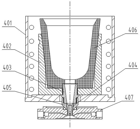
The invention discloses a full-automatic vacuum tight coupling gas atomization device and a method thereof. The full-automatic vacuum tight coupling gas atomization device comprises a smelting chamber, an atomizing chamber, a crucible, a tundish system, a worm gear mechanism, a servo motor, a frequency converter and a central processing system; the smelting chamber and the atomizing chamber are arranged closely and horizontally in up-down parallel, the tundish system is further horizontally arranged on the bottom surface of the inner part of the smelting chamber, an inlet of the upper end of the tundish system communicates with the inner part of the smelting chamber, and an outlet of the lower end of the tundish system communicates with the inner part of the atomizing chamber; the crucibleis further obliquely arranged on one side of the inner part of the smelting chamber, a rotating shaft of the crucible obliquely and downward extends out of the smelting chamber, and is connected withan output end of the servo motor through the worm gear mechanism in a linked mode; and the frequency converter and the central processing system are further arranged on the outer part of the smeltingchamber, and the frequency converter is correspondingly and electrically connected with the servo motor and the central processing system. According to the full-automatic vacuum tight coupling gas atomization device, the full-automatic production of industrial grade gas atomization equipment is achieved.

Description

technical field [0001] The invention relates to the field of preparing metal powder by vacuum atomization, in particular to a fully automatic vacuum close-coupled gas atomization device and a method thereof. Background technique [0002] 3D printing technology is based on digital model files, using powdered metal or plastic and other materials to manufacture products through layer-by-layer accumulation methods, especially suitable for manufacturing customized products with mesh and inner hollow. Compared with conventional technology, this technology does not require the manufacture of special molds and does not generate cutting waste, so it is developing rapidly around the world. At present, 3D printing technology has been widely used in aerospace, medical, mold manufacturing and other fields. Among them, metal 3D printing technology is the leader in the 3D printing industry. The strength and stiffness of products manufactured by this technology can meet the actual requireme...

Claims


Application Information

Patent Timeline
Patent Type & Authority Applications(China)
IPC IPC(8): B22F9/08
CPCB22F9/082B22F2009/0888B22F2009/088Y02P10/25
Inventor 陈洋顾孙望吴文恒卢林张亮郭韶山车鹏张天原张慎云童瑞晗李冬晗
Owner ZHONGTIAN SHANGCAI ADDITIVE MFG CO LTD
Why Eureka
Eureka Blog
Learn More