
Modeling method of MOS device

A technology of MOS devices and modeling methods, applied in special data processing applications, CAD circuit design, etc., can solve problems such as no longer applicable, parasitic inductance can not be ignored, etc., and achieve the effect of wide application range

Pending Publication Date: 2020-11-10
SHANGHAI INTEGRATED CIRCUIT RES & DEV CENT
View PDF0 Cites 3 Cited by
  • Summary
  • Abstract
  • Description
  • Claims
  • Application Information

AI Technical Summary

Problems solved by technology

Among them, in the production of actual devices, the parasitic elements of the source, drain and gate of MOS devices show distributed effects, the parasitic inductance cannot be ignored, and its parasitic resistance also changes with the increase of frequency. The existing MOS devices Typical models no longer apply at high frequencies

Method used


Image

  • Modeling method of MOS device
  • Modeling method of MOS device
  • Modeling method of MOS device

Examples


Embodiment Construction

[0033] In order to make the purpose, technical solution and advantages of the present invention clearer, the specific implementation manners of the present invention will be further described in detail below in conjunction with the accompanying drawings.

[0034] A kind of modeling method of MOS device provided by the invention comprises the following steps:

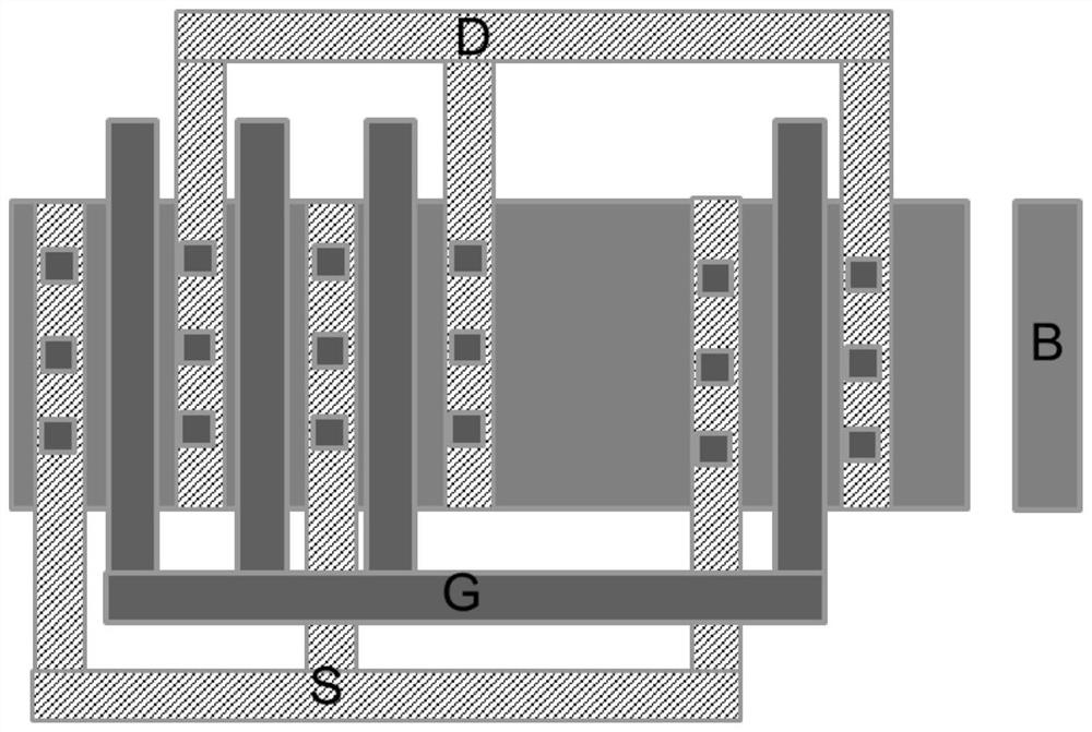
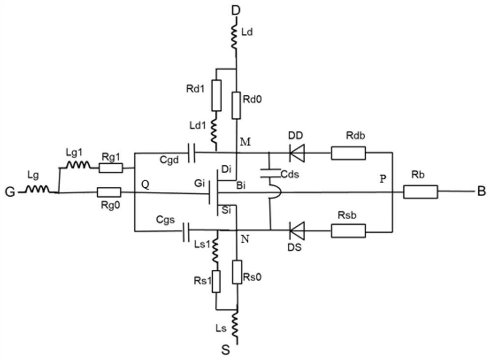
[0035] S01: Construct the model circuit of the MOS device, where the layout structure of the MOS device is as attached figure 1 As shown, including source S, gate G, drain D and substrate B, the corresponding model circuit includes intrinsic transistor, substrate parasitic resistance, parasitic capacitance, parasitic diode, gate parasitic resistance inductance network, source pole parasitic resistance inductance network and drain parasitic resistance inductance network. On the basis of the general structure, the present invention adds a new topological connection structure to the parasitic elements of the gate, source ...


PUM


Abstract

The invention discloses a modeling method of an MOS device, and the method comprises the following steps: S01, constructing a model circuit of the MOS device, wherein the model circuit comprises an intrinsic transistor, a substrate parasitic resistor, a parasitic capacitor, a parasitic diode, a grid parasitic resistor inductance network, a source parasitic resistor inductance network and a drain parasitic resistor inductance network; S02, determining models and size parameters of an intrinsic transistor and a parasitic diode in the model circuit; S03, respectively determining parasitic elementvalues of the source parasitic resistance inductance network and the drain parasitic resistance inductance network by adopting an electromagnetic simulation method; S04, determining parasitic elementvalues of the substrate parasitic resistance, parasitic capacitance and grid parasitic resistance inductance network based on the test data; and S05, substituting the calculated parasitic element value into the model circuit. The model circuit comprises the parasitic resistance inductance network of each connection path, and the model is wider in application range and can be suitable for millimeter waves and other frequency bands.

Description

technical field [0001] The invention belongs to the field of modeling and testing of semiconductor devices, and in particular relates to a modeling method of MOS devices. Background technique [0002] With the continuous advancement of CMOS technology, the characteristic size of transistors has been continuously reduced, and the characteristic frequency ft and maximum oscillation frequency fmax of MOS devices have continued to increase. The operating frequency of RF MOS devices has begun to be used in high-frequency fields such as millimeter waves and terahertz frequency bands. An accurate MOS device model is a prerequisite for product development in the high-frequency field. [0003] With the increase of operating frequency, the distributed effect of parasitic elements in MOS devices becomes more and more significant. The existing RF MOS device models are not accurate enough to model parasitic elements in high-frequency fields such as millimeter waves. At present, there ar...

Claims


Application Information

Patent Timeline
Patent Type & Authority Applications(China)
IPC IPC(8): G06F30/36
CPCG06F30/36Y02E60/00
Inventor 刘林林
Owner SHANGHAI INTEGRATED CIRCUIT RES & DEV CENT
Learn More