3D printing system for dynamic imaging and printing method thereof

A 3D printing and dynamic imaging technology, applied in the field of 3D printing, can solve the problems of large liquid crystal pixel gap, low printing precision, small printing area, etc.

Inactive Publication Date: 2020-11-13
卢振武
View PDF5 Cites 1 Cited by
  • Summary
  • Abstract
  • Description
  • Claims
  • Application Information

AI Technical Summary

Problems solved by technology

The advantages of this technology are: the system structure is simple, the core component is an LCD liquid crystal panel, and the cost is low; but its disadvantages are: the liquid crystal pixel gap is large, the printing accuracy is low; the liquid crystal material is greatly affected by the environment, and the printing system is unstable
The advantages of this technology are: the pixel gap is small, the printing accuracy is high, the DLP chip is sealed and packaged, and the printing system is relatively stable; but its disadvantages are: the exposure

Method used


Image

  • 3D printing system for dynamic imaging and printing method thereof
  • 3D printing system for dynamic imaging and printing method thereof
  • 3D printing system for dynamic imaging and printing method thereof

Examples


Embodiment 1

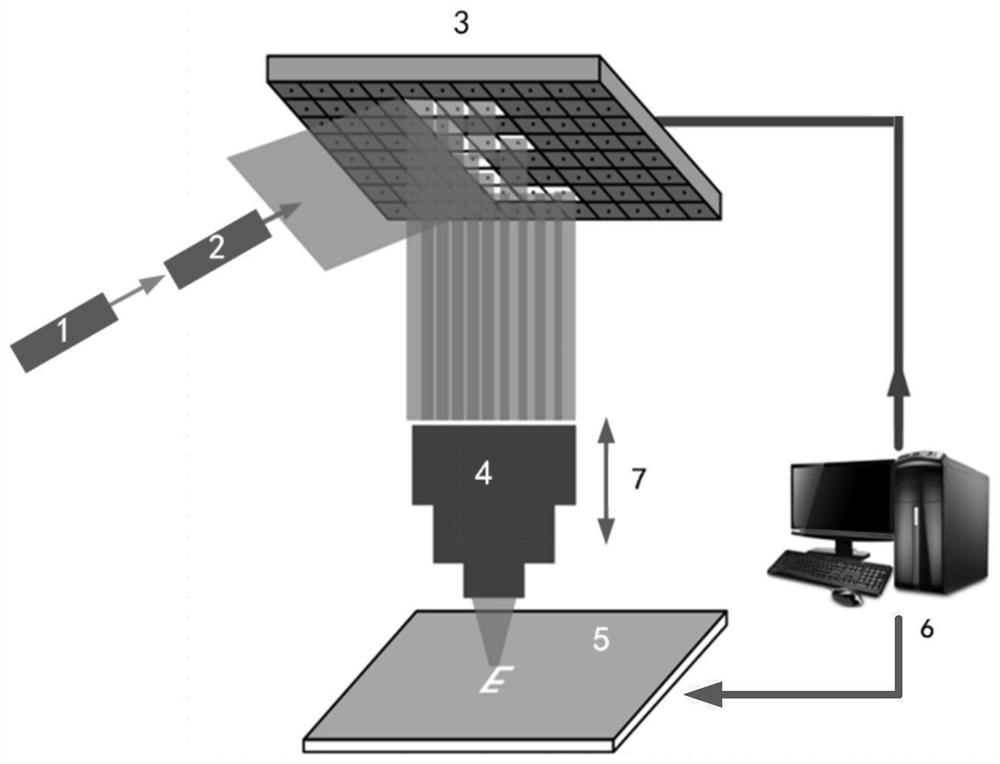
[0032] Such as figure 1 As shown, the direct dynamic imaging 3D printing system adopted in the present invention includes a 405nm wavelength exposure light source 1, an illumination system 2, a spatial light modulator 3, a projection exposure objective lens 4, a two-dimensional displacement platform sample platform 5, and a computer 6; the exposure light source 1 passes through The illumination system 2 irradiates the surface of the spatial light modulator 3 after collimating and shaping the light beam, and irradiates the pattern on the surface of the spatial light modulator to the area to be exposed on the surface 5 of the two-dimensional displacement platform through the projection exposure objective lens 4 . Control the continuous and dynamic loading of graphics on the spatial light modulator 3 so that it is matched synchronously with the scanning of the two-dimensional displacement platform 5, and control the movement of the projection lens in the Z-axis direction 7 (vertic...

Embodiment 2

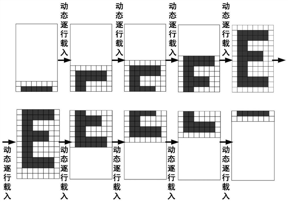
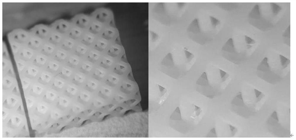
[0037] Such as figure 2 and 3 Shown is the printing process and physical map of the dynamic imaging 3D printing structure, and its processing method is as follows:

[0038]A 405nm wavelength laser with a laser energy of 980mJ is used as the laser light source. The 405nm ultraviolet beam is irradiated onto the surface of the spatial light modulator (DMD, model 9500UV) after being projected through the objective lens, and the computer transmits the digital graphics to the DMD; the laser reflected from the DMD beam, through the self-made projection objective lens with a magnification of 1:1, the rolling image on the DMD surface is dynamically projected onto the two-dimensional displacement platform. 4mJ / cm 2 At this time, the size of the graphics on the DMD after being projected onto the platform through the projection objective lens is about 20mm×10mm, and the graphics scrolling speed is 22mm / s; The scanning movement exposes the dynamic projection graphics to the resin mater...


PUM

PropertyMeasurementUnit
Wavelengthaaaaaaaaaa

Abstract

The invention discloses a 3D printing system for dynamic imaging and a printing method thereof and belongs to the technical field of 3D printing. The printing method comprises the following steps of taking a spatial light modulator as a dynamic pattern generation apparatus; carrying out beam collimation and shaping by an exposure light source through an illuminating system; radiating the surface of the spatial light modulator to radiate the dynamic pattern on the surface of the spatial light modulator to the surface of a two-dimensional displacement platform through a projecting exposure objective; matching continuous loading of the dynamic pattern and scanning movement of the two-dimensional displacement platform synchronously; and further controlling the position of a focal face of a projecting lens for scan exposure layer by layer to achieve high precision, large area and dynamic imaging 3D printing. The system solves the problem that high precision and large area cannot be considered at the same time in a conventional 3D printing process, achieves joint-free high precision 3D printing of a meter-scale structure, and can be widely applied to various industrial manufacturing demands.

Description

technical field [0001] The invention belongs to the technical field of 3D printing, and in particular relates to a dynamic imaging 3D printing system and a printing method thereof. Background technique [0002] With the popularization of 3D printing, 3D printing can be applied in more and more extensive fields, and various 3D printing technologies and equipment have also been developed one after another. Among them, light-curing 3D printing has become the most common 3D printing technology on the market due to its high-quality structure, fine feature size and complex geometry. Its specific technologies mainly include the following three types, namely: LCD (Liquid Crystal Display technology) 3D printing, SLA (laser scanning stereolithography) 3D printing and DLP (digital light processing) 3D printing. [0003] LCD technology is a commonly used 3D printing technology, and it is also an earlier 3D printing technology popularized by the public. This technology uses optical proj...

Claims


Application Information

Patent Timeline
IPC IPC(8): B29C64/264B29C64/268B29C64/129B29C64/135B33Y10/00B33Y30/00B33Y70/00B33Y70/10
CPCB33Y10/00B33Y30/00B33Y70/00B29C64/129B29C64/135B29C64/264B29C64/268B33Y70/10
Inventor 卢振武
Owner 卢振武
Why Eureka
Try Eureka