
System and method based on middle gas suction of compressor and used for liquefied air energy-storage peak regulation

A technology of liquefied air and compressors, which is applied in the direction of compressors, machine operation, and compressors with cascading work, etc. It can solve the problems of limited peak shaving capacity, reduced energy quality, and high average cost, and achieves deep reduction. Effect of cold production cost, reduction of energy transmission loss, reduction of investment and floor space

Active Publication Date: 2020-11-13
XIAN XIRE ENERGY SAVING TECH +1
View PDF9 Cites 0 Cited by
  • Summary
  • Abstract
  • Description
  • Claims
  • Application Information

AI Technical Summary

Problems solved by technology

[0003] At present, the technologies to improve the peak-shaving capability of coal-fired units mainly include electric boiler heat storage technology, water tank heat storage technology, steam turbine steam process transformation technology, electrochemical battery energy storage technology, etc. Electric boiler heat storage technology is to convert electric energy into heat energy. It is used for heating and has strong peak-shaving ability, but the energy quality is greatly reduced, and it is only suitable for cogeneration units. Water tank heat storage technology and steam turbine steam process transformation technology have better thermal economy and relatively low investment, but the peak-shaving ability is limited. , and is only applicable to combined heat and power units. Electrochemical battery energy storage technology has fast response, small size, and short construction period, but has short life, high average cost, and high safety risk. Whether it is suitable for large-scale energy storage implementation still needs engineering demonstration verification

Method used


Image

  • System and method based on middle gas suction of compressor and used for liquefied air energy-storage peak regulation

Examples


Embodiment Construction

[0022] The patent of the present invention will be described in further detail below in conjunction with the accompanying drawings and specific embodiments. The specific embodiments described here are only used to explain the present invention, and are not intended to limit the present invention.

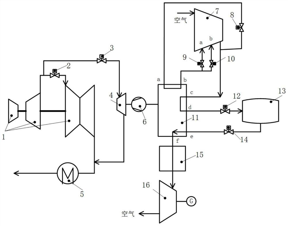
[0023] Such as figure 1 As shown, the present invention is based on a liquefied air energy storage peak-shaving system based on compressor mid-suction, consisting of a first steam turbine unit 1, a first valve 2, a second valve 3, a second steam turbine unit 4, a condenser 5, a refrigeration compression Machine 6, air compressor 7, third valve 8, fourth valve 9, fifth valve 10, cascade refrigeration / cold storage system 11, sixth valve 12, liquid air storage tank 13, seventh valve 14, air heating Device 15 and air expander 16 are formed.

[0024] The first steam turbine unit 1 includes a high-pressure cylinder, a medium-pressure cylinder and a low-pressure cylinder connected in sequ...


PUM


Abstract

The invention discloses a system and method based on middle gas suction of a compressor and used for liquefied air energy-storage peak regulation. The system is composed of a first steam turbine unit,a second steam turbine unit, a steam condenser, a refrigeration compressor, an air compressor, a cascade refrigeration / cold storage system, a liquid air storage tank, an air heating device, an air expander and a control valve. The running method of the system comprises an energy-storage mode and an energy-release mode. According to the system, the cascade refrigeration / cold storage system is driven by virtue of redundant steam, so that the energy transfer loss is reduced, and the cryogenic production cost is greatly reduced; a small part of air from an outlet of the air compressor is cooled to a certain extent through the cascade refrigeration / cold storage system, and then re-enters into different working levels in the air compressor, so that the temperature rise and power consumption ofa compression process are reduced, and the energy-storage efficiency of the system is increased; and meanwhile, an interstage cooler does not need to be arranged again, so that the system investment and the floor area are reduced.

Description

technical field [0001] The invention belongs to the technical field of energy storage peak regulation, and specifically relates to a liquefied air energy storage peak regulation system and method based on compressor intermediate suction, which is suitable for various thermal power plants with coal-fired units as typical, and can improve the efficiency of coal-fired units. Peak shaving capability and economy of energy storage system. Background technique [0002] At present, my country's wind energy, solar energy and other renewable energy sources are developing rapidly year by year. In addition, the electricity consumption of the whole society is increasing year by year, and the peak-to-valley difference in power consumption of the power grid is increasing. [0003] At present, the technologies to improve the peak-shaving capability of coal-fired units mainly include electric boiler heat storage technology, water tank heat storage technology, steam turbine steam process tran...

Claims


Application Information

Patent Timeline
IPC IPC(8): F25B7/00F25B27/02F01D13/00F01D15/08F01D17/10F01K11/02F04B39/00
CPCF25B7/00F25B27/02F01D13/00F01D15/08F01D17/10F01K11/02F04B39/00F25J1/0012F25J1/0282F25J1/0251F25J2230/04F25J2245/40F25J2230/30F25J2270/12F25J2240/90
Inventor 张建元居文平常东锋王伟雒青范庆伟黄嘉驷
Owner XIAN XIRE ENERGY SAVING TECH
Learn More