
Steel plate rust removal equipment and steel plate rust removal method

A technology for steel plates and equipment, applied in the field of steel plate rust removal, can solve the problems of small contact area between the polisher and steel plate, unsuitable for rust removal work, general rust removal effect, etc., to achieve rapid and effective rust removal, good rust removal effect, Fast and effective removal

Pending Publication Date: 2020-11-17
SHANGHAI STRONG FOUND ENG
View PDF0 Cites 0 Cited by
  • Summary
  • Abstract
  • Description
  • Claims
  • Application Information

AI Technical Summary

Problems solved by technology

[0002] The problem of steel rusting seems to be a common problem in the steel industry at present. At present, the common rust removal methods on the market include manual angle grinder grinding and rust removal, steel rust removal machine rust removal, sandblasting machine shot blasting machine rust removal and steel bar rust removal There are several methods of derusting with chemical agents, which are not suitable for a large number of derusting work, and the cost of derusting is relatively high
[0003] Under the environment of the construction industry, the construction site is required to have higher timeliness, safety and reliability during the construction process. At present, the working environment on the construction site is harsh, the rust removal method is extremely slow, the rust removal efficiency is low and there are quality defects, especially When using a grinder to remove rust on some steel plates, the efficiency is improved, but if the grinder is not operated properly, the surface of the pipe will be more or less damaged, and the rust removal is uneven, and the grinder is in contact with the steel plate The area is small, the rust removal efficiency is not high, the rust removal effect is general, time-consuming and labor-intensive, to a certain extent, affects the construction progress

Method used


Image

  • Steel plate rust removal equipment and steel plate rust removal method
  • Steel plate rust removal equipment and steel plate rust removal method

Examples


Embodiment Construction

[0019] In order to make the technical means, creative features, goals and effects achieved by the present invention easy to understand, the present invention will be further described below in conjunction with specific illustrations.

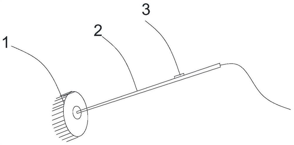
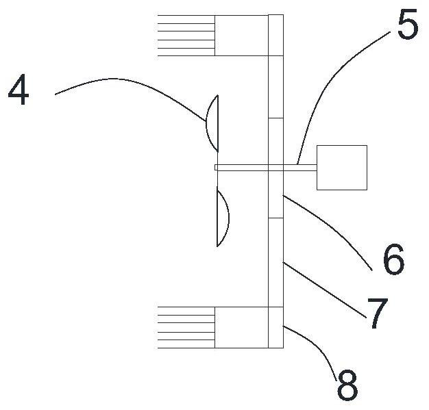
[0020] see figure 1 , a steel plate derusting equipment, is a single-handed derusting machine, including a grinding and cleaning head 1, the grinding and cleaning head is a disc, the disc is provided with a replaceable wire brush, and the disc is connected to a drive motor, The motor drives the disc to rotate, so that the wire brush rubs on the steel plate to remove rust, and the wire brush is designed as a replaceable structure. When the wire brush is worn out, it can be replaced conveniently; the grinding and cleaning head is connected to a long handle 2, and the rear end of the handle is connected to Cable is arranged, and control switch 3 is arranged on the handle. Control switch 3 can control the starting and closing of grinding and cleani...


PUM


Abstract

The invention provides steel plate rust removal equipment. The steel plate rust removal equipment comprises a grinding and cleaning head, wherein the grinding and cleaning head is a disc, a replaceable steel wire brush is arranged on the disc, and the disc is connected with a driving motor; the grinding and cleaning head is connected with a long handle, a cable is connected to the rear end of thehandle, and a control switch is arranged on the handle; and a blowing nozzle is arranged in the middle of the grinding and cleaning head, fan blades are arranged inside the blowing nozzle, and the fanblades are connected with a motor shaft of the driving motor through a gear. The steel plate dust removal method comprises the steps that during rust removal, firstly, a rust remover is uniformly sprayed on a steel plate needing rust removal; then rust removing and grinding are carried out on the steel plate by using the rust removal equipment with the steel wire brush; and finally, antirust paint is sprayed on the steel plate.

Description

technical field [0001] The invention relates to the technical field of civil engineering, in particular to a steel plate derusting technology for bridge erection. Background technique [0002] The problem of steel rusting seems to be a common problem in the steel industry at present. At present, the common rust removal methods on the market include manual angle grinder grinding and rust removal, steel rust removal machine rust removal, sandblasting machine shot blasting machine rust removal and steel bar rust removal There are several methods of derusting by agent, which are not suitable for a large amount of derusting work, and the cost of derusting is relatively high. [0003] Under the environment of the construction industry, the construction site is required to have higher timeliness, safety and reliability during the construction process. At present, the working environment on the construction site is harsh, the rust removal method is extremely slow, the rust removal e...

Claims


Application Information

Patent Timeline
Patent Type & Authority Applications(China)
IPC IPC(8): B24B23/02B24B27/033B24B55/10C23G1/08
CPCB24B23/02B24B27/033B24B55/102C23G1/08
Inventor 宋阳陈彦凤段先林
Owner SHANGHAI STRONG FOUND ENG
Learn More