
Electric instructional car transmission system

A technology of electric coaching vehicle and transmission system, which is applied in vehicle components, control devices, transportation and packaging, etc., and can solve the problem of difficult to use engine and multi-speed transmission transmission system, pure electric vehicles have not been widely promoted, transmission shaft alignment, etc. Problems such as difficulty in assembling in the middle, achieve the effect of low production cost, high centering precision, and low difficulty in assembling

Pending Publication Date: 2020-11-20
DONGFENG AUTOMOBILE COMPANY
View PDF0 Cites 0 Cited by
  • Summary
  • Abstract
  • Description
  • Claims
  • Application Information

AI Technical Summary

Problems solved by technology

[0002] The driving school's coach cars are mainly manual transmission models, and more than 70% of the time the coach cars are used in the venue. During the training, the cars are in low gears, low speeds, and frequently start and stop operating conditions, resulting in low-efficiency engine work. interval, high fuel consumption and heavy pollution
Pure electric vehicles have the characteristics of zero emission and no pollution, but currently pure electric vehicles have not been widely promoted in the driving school market
[0003] The existing electric vehicles are mainly automatic transmission models. The technical solution is a motor and a single-speed ratio reducer structure. There are fewer manual transmission models. Due to the limitation of the motor structure, the motor shaft cannot be directly connected to the flywheel like the engine crankshaft. It is difficult to use traditional engines and multiple gears. Gearbox transmission system, if forcibly applied, will cause the gearbox shaft centering assembly difficulties, transmission system vibration and abnormal sound defects

Method used


Image

  • Electric instructional car transmission system
  • Electric instructional car transmission system
  • Electric instructional car transmission system

Examples


Embodiment 1

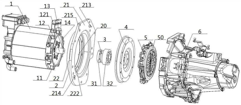
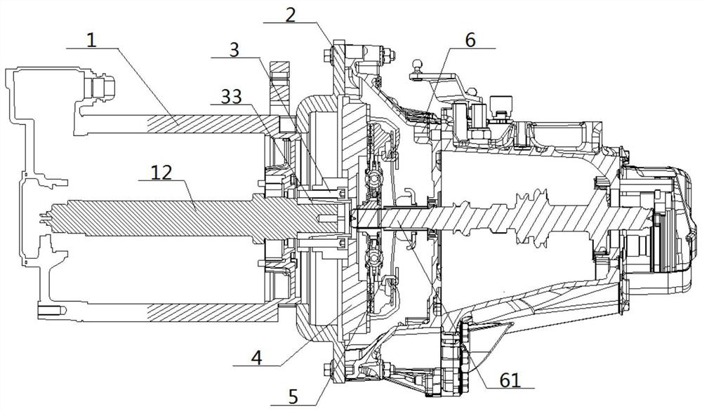
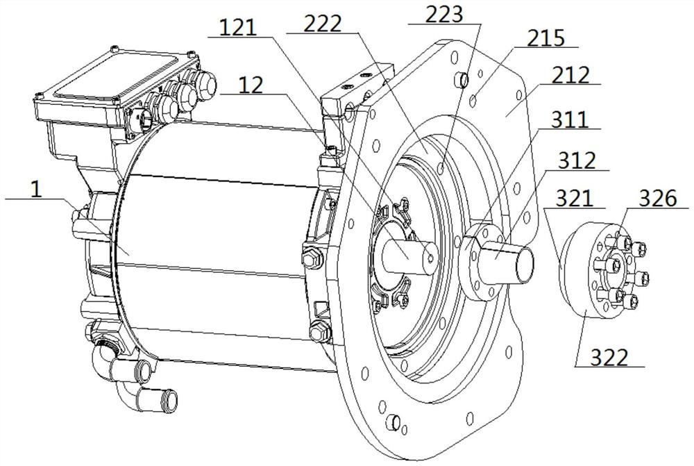
[0056] see figure 1 — Figure 13 , a transmission system for an electric coach, comprising a flywheel 4, a clutch assembly 5 and a gearbox 6 arranged in sequence, and a gearbox shaft 61 is arranged in the gearbox 6; the transmission system for an electric coach also includes a motor 1, Connecting the flange 2 and the coupling 3, the right end of the motor 1 is provided with the outer end surface 11 of the motor and the output shaft 12 protruding in the middle. The middle part of the flange 2 is provided with a flange cavity 20; the outer end surface 11 of the motor is centered and connected with the left end of the connecting flange 2, and the right end of the connecting flange 2 is centered and connected with the left end of the gearbox 6. The output shaft 12 is connected through The coupling 3 is centeredly connected with the left end of the flywheel 4, and the right end of the flywheel 4 is centeredly connected with the clutch assembly 5. The left end of the first shaft 61...

Embodiment 2

[0058] Basic content is the same as embodiment 1, the difference is:

[0059] see Figure 4 and Figure 5 , the clutch assembly 5 includes a driven plate 51 and a pressure plate 52, the middle part of the driven plate 51 is provided with a slave spline hole 511, the middle part of the pressure plate 52 is provided with a shaft hole 521, and a shaft hole 521 is coaxially connected with the secondary spline hole 511 to form a spline hole 50; on the plate surface of the pressure plate 52, there are a plurality of connecting wheels correspondingly connected with the wheel connecting hole 521 around the position of the shaft hole 521 Hole 53.

[0060] When assembling, insert the thinner end of the tooling pin 7 into the inner shaft hole 121 in the middle of the output shaft 12, then put the driven plate 51 and the pressure plate 52 on the tooling pin 7 in sequence, and then tighten the pressure plate 52 bolts, and then take out the tooling pin 7 to ensure that the secondary spli...

Embodiment 3

[0062] Basic content is the same as embodiment 1, the difference is:

[0063] see Figure 8 — Figure 11 , the output shaft 12 is a cylindrical structure with equal diameter, the coupling 3 includes an inner coupling 31 and an outer coupling 32, the inner coupling 31 includes an inner ring seat 311 and an inner cylinder 312, the inner The cylinder 312 is a frustum of conical structure with wide left and narrow right. The inner cylinder 312 is provided with an inner cylinder cavity 313. The inner ring seat 311 is provided with an inner ring seat cavity 314 communicating with the inner cylinder body cavity 313. The inner ring seat 311 A plurality of inner ring connection holes 315 are opened around the inner cylinder 312 on the seat surface of the inner cylinder, and the inner cavity wall of the inner cylinder cavity 313 is nested with the side circumference of the output shaft 12; the outer coupler 32 includes an outer left ring seat 321 and the outer right ring seat 322, the...


PUM


Abstract

The invention discloses an electric instructional car transmission system. The system comprises a motor, a connecting flange, a coupling, a flywheel, a clutch assembly and a gearbox which are arrangedin sequence, wherein the right end of the motor is provided with a motor outer end face and a convex output shaft arranged in the middle of the motor outer end face. An inner shaft hole is formed inthe middle of the output shaft; a flange cavity is formed in the middle of the connecting flange; the outer end surface of the motor is centered and connected with the left end of the connecting flange; the right end of the connecting flange is in centering connection with the left end of the gearbox; the output shaft is connected with the left end of the flywheel in a centered mode through the coupler, the right end of the flywheel is connected with the clutch assembly in a centered mode, the left end of the first gearbox shaft is inserted into a spline forming hole in the middle of the clutch assembly, the coupler, the flywheel and the clutch assembly are all located in the flange cavity, and the output shaft, the connecting flange and the first gearbox shaft are coaxially arranged. According to the system, the centering precision is high, vibration abnormal sounds of a transmission system are not likely to be caused, operation is easy, and the manufacturing cost and the assembling cost are low.

Description

technical field [0001] The invention relates to a vehicle transmission system, which belongs to the technical field of electric vehicles, in particular to an electric coach vehicle transmission system. Background technique [0002] The driving school's coach cars are mainly manual transmission models, and more than 70% of the time the coach cars are used in the venue. During the training, the cars are in low gears, low speeds, and frequently start and stop operating conditions, resulting in low-efficiency engine work. interval, high fuel consumption and heavy pollution. Pure electric vehicles have the characteristics of zero emission and no pollution, but currently pure electric vehicles have not been widely promoted in the driving school market. [0003] The existing electric vehicles are mainly automatic transmission models. The technical solution is a motor and a single-speed ratio reducer structure. There are fewer manual transmission models. Due to the limitation of th...

Claims


Application Information

Patent Timeline
IPC IPC(8): B60K17/00B60K17/02B60K17/26B60K17/28
CPCB60K17/00B60K17/02B60K17/26B60K17/28
Inventor 艾宝群郑兆刚赵健生秦三元郭良华冯源王为才肖映元薛传亮凌帆唐剑波尚天洋王磊
Owner DONGFENG AUTOMOBILE COMPANY
Learn More