Tar residue resource utilization process

A technology for tar residue and resource utilization is applied in the field of tar residue resource utilization technology to achieve the effect of reducing use and increasing added value

Inactive Publication Date: 2020-11-20
新疆新业能源化工有限责任公司
View PDF10 Cites 4 Cited by
  • Summary
  • Abstract
  • Description
  • Claims
  • Application Information

AI Technical Summary

Problems solved by technology

[0005] In order to solve the defect that the existing tar residues cannot be better utilized as resources, the purpose of the present invention is to provide a process for resource utilization of tar residues

Method used


Image

  • Tar residue resource utilization process
  • Tar residue resource utilization process
  • Tar residue resource utilization process

Examples


Embodiment 1

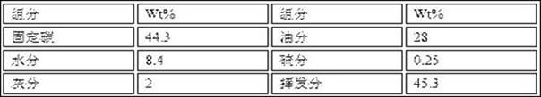
[0026] The raw material characteristics of tar slag are as shown in table 1 in this example:

[0027] Table 1 Raw material characteristics of tar residue

[0028]

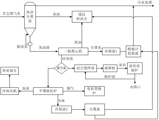
[0029] As shown in Table 1, the present invention provides a tar residue resource utilization process of the present invention, which includes the following steps:

[0030] (1) The dusty gas water is cooled and flashed and sent to the tar separator. The tar separator uses the different densities of the components in the dusty gas water to separate tar residue, tar, and water into three different substances; tar and water pass through the tar The upper part of the separator is separated, and the tar residue remains at the bottom of the cone of the tar separator;

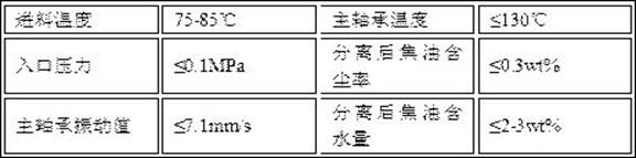
[0031] (2) The tar slag is sent to the three-phase centrifuge through the delivery pump at the 1.5-meter opening of the cone bottom of the tar separator, and part of it is transported back to the circular material slag at the cone bottom, and the large...

Embodiment 2

[0046] Step (1) in embodiment two is exactly the same as embodiment one, and the characteristics of tar residue are as shown in table 5:

[0047] Table 5 Raw material characteristics of tar residue

[0048] components Wt% components Wt% fixed carbon 36.6 Oil 9.8 moisture 14.1 Sulfur content 0.24 Ash 11.8 Volatile matter 37.5

[0049] (2) The tar slag is sent to the three-phase centrifuge through the delivery pump at the 1.5-meter opening of the cone bottom of the tar separator, and part of it is transported back to the circular material slag at the cone bottom, and the large particle dust settled at the cone bottom is continuously discharged. Rinse and dilute so that the tar residue at the bottom is evenly mixed, and the tar residue is sent into a three-phase centrifuge to obtain tar, separated water, and solid residue after separation; the parameters of the three-phase centrifuge are shown in Table 6, and the three-phase centrifu...


PUM


Abstract

The invention provides a tar residue resource utilization process. Tar, solid residues and water which are obtained after tar residues in the coal gasification process are centrifuged through three-phase centrifugation. Judging the next solid slag treatment process according to the carbon content of the separated solid slag, and carrying out dry distillation on the solid slag to prepare coke whenthe carbon content of the solid slag is greater than or equal to 45%; when the carbon content of the solid slag is less than 45%, the solid slag and the fluidized bed boiler slag are mixed and crushedto serve as a fluidized bed material to enter a furnace for combustion, and phenol ammonia in water generated in the process is removed through a phenol ammonia recovery device. In the process, the tar residue inlet pressure of a three-phase centrifugal machine is controlled to be 0-0.1 Mpa, the inlet temperature is controlled to be 65-90 DEG C, the rotating speed of the centrifugal machine is 2000-3500r / min, and the differential speed is 17-40r / min; wherein the dry distillation temperature is 650 + / -50 DEG C, and the dry distillation time is 2 hours; after solid slag and fluidized bed boilerslag are mixed and stirred, solid particles with the diameter of 6-8 mm are crushed to serve as bed materials; and the phenol-ammonia recovery device controls the phenol content at an outlet to be less than or equal to 800mg / L and the ammonia content to be less than or equal to 300mg / L. The process is high in tar residue treatment efficiency, less in pollution, energy-saving and emission-reducing.

Description

technical field [0001] The invention relates to the field of resource utilization of tar slag produced in the coal gasification industry, in particular, the invention relates to a process for resource utilization of tar slag. Background technique [0002] In the coal gasification process, the pressurized gasification process produces organic compounds with high boiling points. After washing and condensing with water, it is mixed with coal powder and solid particles in the gas to form dusty gas water. The pressure of dusty gas water is 3.8MPa. The temperature is 180°C. After cooling and flashing, the dusty gas water enters the tar separator by gravity, and then the tar and tar residue of heavy components are separated. Generally, the tar residue produced after coal gasification is treated by stacking and storing the tar residue as waste, or selling the tar residue to low-value-added processing industries such as asphalt for processing. [0003] Chinese invention patent CN10...

Claims


Application Information

Patent Timeline
Patent Type & Authority Applications(China)
IPC IPC(8): C10C1/00C10C1/02C10B53/00F23G7/06
CPCC10B53/00C10C1/00C10C1/02F23G7/06
Inventor 李兵王峰马金荣曾伟焦金峰李月王建渊宋丽萍
Owner 新疆新业能源化工有限责任公司
Why Eureka
Try Eureka