Calcination furnace waste heat power generation system

A technology of waste heat power generation and calcination furnace, which is applied in the direction of furnace, waste heat treatment, furnace components, etc., can solve the problems of poor synergistic purification effect of various pollutants, ineffective utilization, environmental heat pollution, etc., to reduce heat pollution and Waste gas pollution, improving the economic benefits of enterprises, and the effect of efficient utilization

Inactive Publication Date: 2020-11-20
河南英利新材料有限公司
View PDF5 Cites 2 Cited by
  • Summary
  • Abstract
  • Description
  • Claims
  • Application Information

AI Technical Summary

Problems solved by technology

This kind of cooling method, which is common in the domestic carbon industry, not only evaporates a large amount of water resources, but also causes thermal pollution to the environment.
[0003] At present, the waste heat in the discharge and flue gas of the carbon calciner has not been effectively utilized, and the synergistic purification effect on various pollutants in the flue gas is poor, which needs to be improved urgently

Method used


Image

  • Calcination furnace waste heat power generation system
  • Calcination furnace waste heat power generation system

Examples


Embodiment

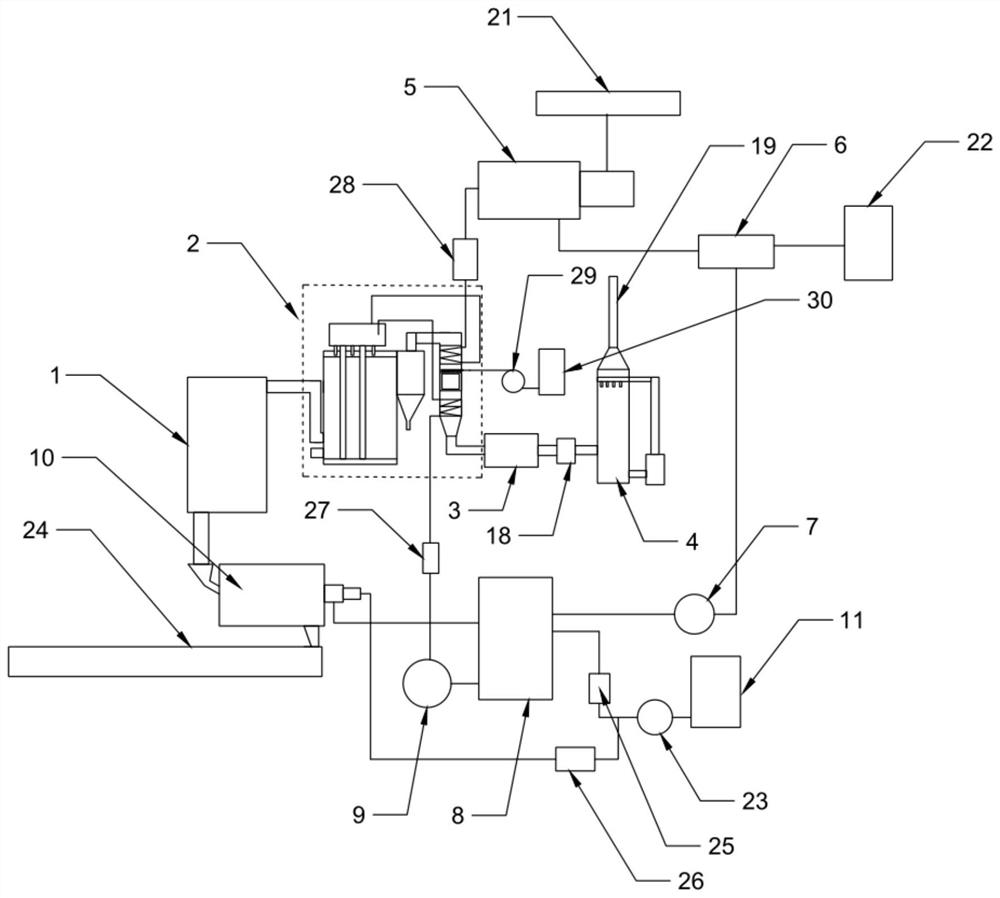
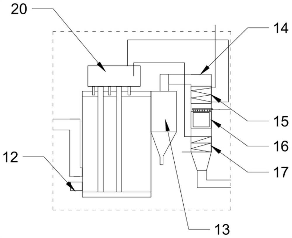
[0017] Such as Figure 1~2 As shown, the present invention provides a calciner waste heat power generation system, including a calciner 1, a flue gas waste heat boiler 2, a bag filter 3, a desulfurization tower 4, a turbogenerator set 5, a condenser 6, a condensate pump 7, Deaerator 8, feed water pump 9, drum slag cooling machine 10 and desalinated water tank 11, the exhaust port of the calciner 1 is connected with the air inlet of the flue gas waste heat boiler 2, and the discharge port of the calciner 1 It is connected with the feeding end of the drum cooling slag machine 10, and a conveying belt conveyor 24 is provided under the discharge end of the drum cooling slag machine 10, and the flue gas waste heat boiler 2 is equipped with a The gas burner 12 of the flue gas waste heat boiler 2 is connected with a cyclone separator 13 at the furnace outlet of the flue gas waste heat boiler 2, and the exhaust end of the cyclone separator 13 is connected with the tail shaft 14 of the...


PUM


Abstract

The invention relates to a calcination furnace waste heat power generation system, and belongs to the technical field of energy saving devices. The calcination furnace waste heat power generation system comprises a calcination furnace, a smoke waste heat boiler, a bag type dust remover, a desulfurizing tower, a steam turbine generator unit, a steam condenser, a condensate pump, a deaerator, a feedpump, a roller slag cooler and a demineralized water tank. An exhaust outlet of the calcination furnace communicates with the smoke waste heat boiler, and a discharging outlet of the calcination furnace communicates with the roller slag cooler. A fuel gas spark plug is arranged in the smoke waste heat boiler, and a combustion chamber outlet of the smoke waste heat boiler is connected with a cyclone separator. A superheater, a denitration device and a smoke cooler are arranged in a tail vertical shaft of the smoke waste heat boiler, and the exhaust end of the tail vertical shaft communicates with the bag type dust remover through a flue. The bag type dust remover communicates with the desulfurizing tower through an induced draft fan, and the steam exhaust end of the superheater is connected with a steam inlet door of the steam turbine generator unit through a steam pipe. By the adoption of the calcination furnace waste heat power generation system, the waste heat in discharged materials and discharged smoke of the carbon calcination furnace can be converted into the electric energy, and efficient and collaborative purification of various pollutants in the smoke of the calcination furnace is achieved.

Description

technical field [0001] The invention belongs to the technical field of energy-saving devices, and in particular relates to a calciner waste heat power generation system. Background technique [0002] After the petroleum coke is calcined in the carbon calciner, the temperature of the discharge (calcined coke) is about 1000°C. According to the heat balance calculation, the heat absorbed by the calcining of raw materials only accounts for 33.5% of the calciner’s thermal expenditure, and is taken away by the calcined flue gas The heat accounted for 47.9% of the thermal expenditure of the entire calciner. The flue gas contains dust, asphalt fume, sulfur dioxide, nitrogen oxides, etc. The flue gas volume is large, the concentration of pollutants is high, and it contains a variety of carcinogenic components. Many manufacturers use water cooling to cool the discharged material to below 200°C, and discharge it into the vibrating screen and transmission belt to achieve the purpose of...

Claims


Application Information

Patent Timeline
Patent Type & Authority Applications(China)
IPC IPC(8): F27D17/00F01K11/00F01D15/10
CPCF27D17/004F27D17/008F01K11/00F01D15/10F27D2017/006Y02P10/25
Inventor 赵臣全赵应强赵应战刘俊峰
Owner 河南英利新材料有限公司
Why Eureka
Try Eureka