Current control method of cascaded sub-module working condition simulation system suitable for NLC

A technology of working condition simulation and current control, which is applied in the direction of adaptive control, electric controller, general control system, etc., can solve the problems of increased control complexity, simulation test circuit manufacturing cost, reduction of auxiliary circuit and pulse voltage synchronization, auxiliary circuit Unable to well offset pulse voltage interference and other issues, to achieve the effect of offsetting pulse voltage interference, reducing complexity, and avoiding distortion

Active Publication Date: 2020-11-20
SHANGHAI JIAOTONG UNIV
View PDF12 Cites 3 Cited by
  • Summary
  • Abstract
  • Description
  • Claims
  • Application Information

AI Technical Summary

Problems solved by technology

However, the additional control circuit increases the complexity of the control and the manufacturing cost of the analog test circuit, and the control delay caused by the dead zone of the switch will reduce the synchronization between the auxiliary circuit and the pulse voltage, which will cause the auxiliary circuit to be unable to well offset Interference with pulse voltage

Method used


Image

  • Current control method of cascaded sub-module working condition simulation system suitable for NLC
  • Current control method of cascaded sub-module working condition simulation system suitable for NLC
  • Current control method of cascaded sub-module working condition simulation system suitable for NLC

Examples


Embodiment Construction

[0061] The following is a detailed description of the embodiments of the present invention: this embodiment is implemented on the premise of the technical solution of the present invention, and provides detailed implementation methods and specific operation processes. It should be noted that those skilled in the art can make several modifications and improvements without departing from the concept of the present invention, and these all belong to the protection scope of the present invention.

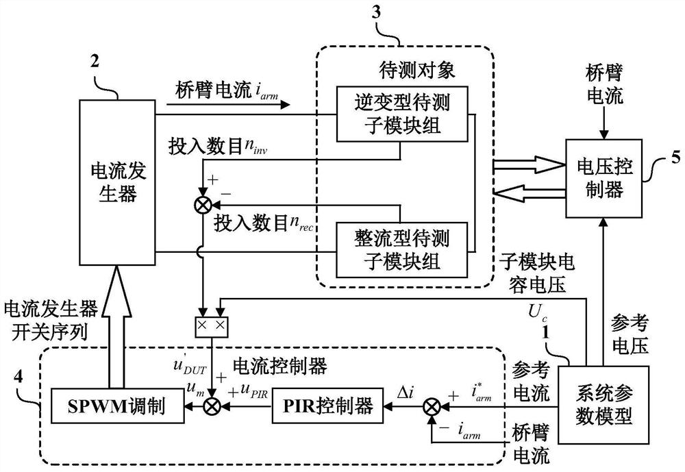
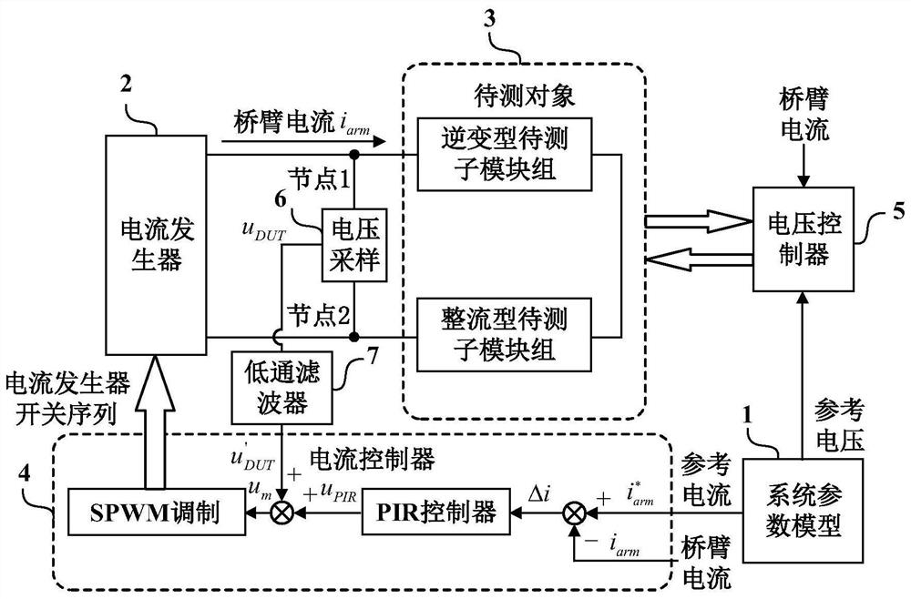
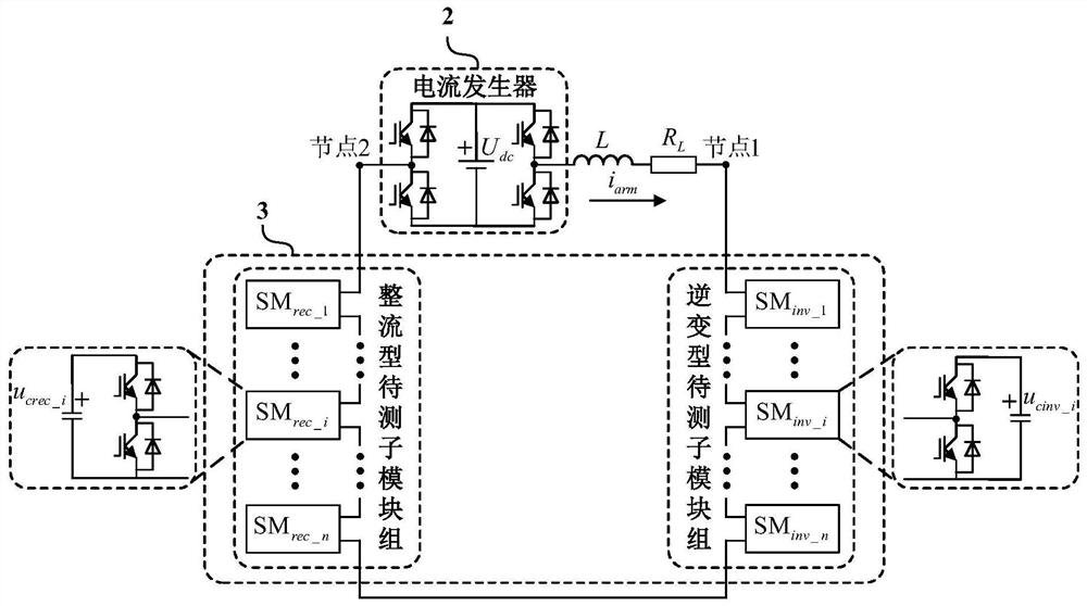
[0062] An embodiment of the present invention provides a current control method applicable to the NLC cascaded converter sub-module working condition simulation system. The method adopts the feedforward voltage compensation method, and compensates the feedforward voltage in the current controller to offset The pulse voltage interference of the port of the object under test caused by the nearest level approximation modulation. This method is suitable for a cascaded converter sub-module o...


PUM


Abstract

The invention provides a current control method of a cascaded converter sub-module working condition simulation system suitable for NLC, and the method is characterized by compensating a feed-forwardvoltage in a current controller to counteract the pulse voltage interference, caused by the nearest level control, of a to-be-measured object port, wherein the feed-forward voltage for compensating isgenerated through the following methods: method 1, calculating the difference value of the numbers of input sub-modules of two sub-module groups to be measured, and multiplying the difference value by the capacitor voltage of a single sub-module so as to generate the feed-forward voltage; and the method 2 comprises the following steps: sampling a voltage signal of a port of a to-be-measured object, carrying out low-pass filtering on the voltage signal, and taking the filtered voltage signal as the feed-forward voltage; and the feed-forward voltage is compensated into the current controller, so that current distortion caused by pulse voltage interference is avoided. Meanwhile, the invention provides a cascaded converter sub-module working condition simulation system and a sub-module test method. According to the invention, the working condition simulation of the cascaded converter sub-module based on nearest level control can be better realized.

Description

technical field [0001] The present invention relates to the technical field of power electronics, in particular, to a current control method for a cascaded sub-module operating condition simulation system applicable to NLC (Nearest Level Approximation Modulation), and a cascaded sub-module based on the current control method. Module working condition simulation system and testing method. Background technique [0002] In recent years, cascaded converters have been widely used in medium and high voltage power transmission occasions due to their modularization and easy expansion. With the continuous improvement of the capacity and voltage level of cascaded converters, the reliability evaluation and detection of cascaded converters during operation has attracted more and more attention. In order to evaluate and detect the reliability of cascaded converters in the early stage, it is often necessary to build a complete cascaded converter system, but because the reliability of cas...

Claims


Application Information

Patent Timeline
Patent Type & Authority Applications(China)
IPC IPC(8): G01R31/00G05B11/42G05F1/46G05B13/04H02M5/458
CPCG01R31/00G05B11/42G05B13/042G05F1/46H02M5/458H02M1/007Y02B70/10
Inventor 马柯李恩溢蔡旭
Owner SHANGHAI JIAOTONG UNIV
Why Eureka
Try Eureka