A thermal power plant combined heat pipe flue gas waste heat recovery device

A waste heat recovery and recovery device technology, which is applied to indirect heat exchangers, heat exchange equipment, heat exchanger shells, etc., can solve the problem of inability to perform gas temperature control at the heat absorption end, inability to accurately control heat exchange energy, and low energy conversion rate and other problems, to achieve the effect of easy maintenance and replacement, improvement of waste heat recovery efficiency, and simple cleaning

Active Publication Date: 2022-02-18
HUAINAN TIANJIAAN POWER GENERATION PLANT ANHUI ELECTRIC POWER CO LTD
View PDF7 Cites 0 Cited by
  • Summary
  • Abstract
  • Description
  • Claims
  • Application Information

AI Technical Summary

Problems solved by technology

[0005] However, the existing flue gas waste heat recovery devices in thermal power plants generally adopt the heat pipe recovery method, the structure is too simple, the practicability is low, the energy conversion rate is low, and the heat exchange energy cannot be precisely controlled, that is, the gas at the heat absorption end cannot be controlled. Temperature control, low practicability. In addition, the traditional heat pipe waste heat recovery device can only realize a single "gas-gas" or "gas-liquid" waste heat recovery function, which has certain defects.

Method used


Image

  • A thermal power plant combined heat pipe flue gas waste heat recovery device
  • A thermal power plant combined heat pipe flue gas waste heat recovery device
  • A thermal power plant combined heat pipe flue gas waste heat recovery device

Examples


Embodiment Construction

[0029] The following will clearly and completely describe the technical solutions in the embodiments of the present invention with reference to the accompanying drawings in the embodiments of the present invention. Obviously, the described embodiments are only some, not all, embodiments of the present invention. Based on the embodiments of the present invention, all other embodiments obtained by persons of ordinary skill in the art without making creative efforts belong to the protection scope of the present invention.

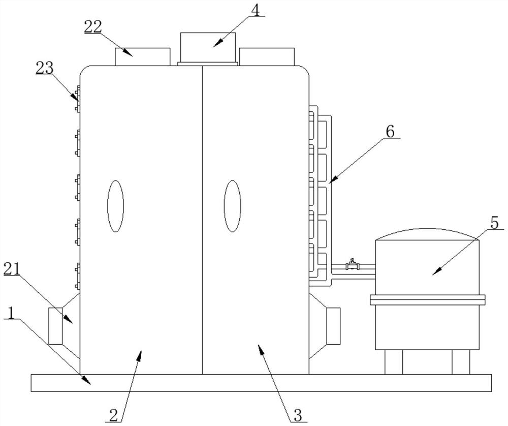
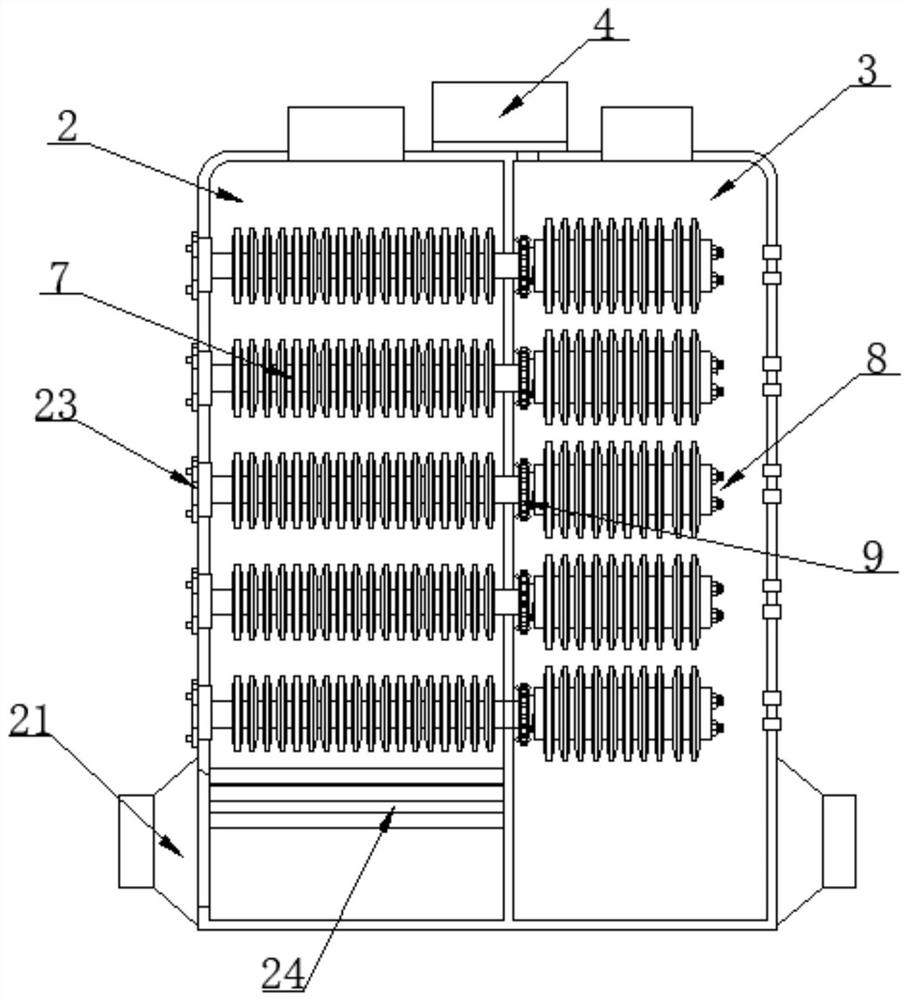
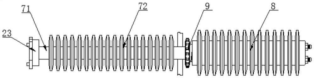
[0030] as attached Figure 1-7 A thermal power plant combined heat pipe flue gas waste heat recovery device shown includes a mounting base 1, a flue gas discharge bin 2 and a waste heat recovery bin 3, and the flue gas discharge bin 2 and the waste heat recovery bin 3 are fixedly installed on the top of the mounting base 1. On the side, the side and the top surface of the flue gas discharge chamber 2 and the waste heat recovery chamber 3 are provided with an i...


PUM


Abstract

The invention discloses a thermal power plant combined heat pipe flue gas waste heat recovery device, specifically relates to the field of waste heat recovery, including a mounting seat, a flue gas discharge bin and a waste heat recovery bin. One side of the discharge bin and the waste heat recovery bin are attached to each other, and a combined heat pipe is installed through the inside of the flue gas discharge bin and the waste heat recovery bin. , the surface of the threaded drive sleeve is movably socketed with a heat exchange sleeve assembly. The invention sets a new combined heat pipe structure, uses mechanical control components to actively change the volume of the heat transfer liquid flow inside the heat exchange pipe sleeve assembly, and changes the exposed length of the heat pipe end inside the waste heat recovery chamber, so as to realize the control of heat exchange efficiency and change the heat recovery air flow The temperature can achieve precise temperature control, facilitate the use of recovered heat energy, and improve the practicability of the waste heat recovery device.

Description

technical field [0001] The invention relates to the technical field of waste heat recovery, in particular to a combined heat pipe flue gas waste heat recovery device of a thermal power plant. Background technique [0002] In recent years, my country's energy demand has shown a rigid growth. Due to the constraints of domestic resource support capabilities and environmental capacity, as well as global energy security and the impact of climate change, resource and environmental constraints have become increasingly intensified. The situation facing energy conservation and emission reduction is very severe. In the production process of thermal power plants , Coal-fired boilers generally have problems such as low heat utilization rate, high waste heat temperature of exhaust flue gas, and high content of polluting gases in flue gas. The use of waste heat recovery system can effectively solve the above problems. [0003] Waste heat resources are secondary resources, which are energy ...

Claims


Application Information

Patent Timeline
Patent Type & Authority Patents(China)
IPC IPC(8): F28D15/02F28D15/06F28F9/26F28F19/01F23J15/06
CPCF28D15/0275F28D15/06F28F9/26F28F19/01F23J15/06Y02E20/30
Inventor 刘彬杨泉胡鲲刘刚王荣胜
Owner HUAINAN TIANJIAAN POWER GENERATION PLANT ANHUI ELECTRIC POWER CO LTD
Why Eureka
Try Eureka