
Adaptive continuous phase hydraulic transmission oil pumping machine

A hydraulic transmission and self-adaptive technology, applied in the direction of production fluid, drilling equipment, wellbore/well components, etc., can solve the problems of parameter drift, underground reservoir heterogeneity, high system cost, etc., and achieve the effect of equipment protection

Pending Publication Date: 2020-11-27
宋志亮
View PDF0 Cites 1 Cited by
  • Summary
  • Abstract
  • Description
  • Claims
  • Application Information

AI Technical Summary

Problems solved by technology

It is easy to cause the inhomogeneity of the viscosity of the underground reservoir, it is difficult to ensure the normal operation of the pumping unit, the downstroke of the oil well sucker rod is blocked, the speed becomes slow, the original balance is lost, and the balance load increases. At this time, Due to the mechanical transmission of the traditional beam pumping unit, the oil well sucker rod will be lifted up before the downstroke of the oil well sucker rod is completed. The installed power of the traditional beam pumping unit is generally relatively large. The electric motor forcibly lifts the balance load, which greatly increases the power consumption. When various types of tower pumping units currently in operation encounter this problem, the power of the motor will be insufficient and the balance box cannot be lifted. power increase
At present, various types of tower pumping units generally adopt frequency conversion speed regulation control system in order to adjust stroke times and strokes conveniently. As the viscosity of heavy oil increases, it is impossible to follow the downstroke of oil well sucker rods.
Frequency conversion speed regulation control system will have parameter drift phenomenon in harsh environment, the cost of the system is high, the maintenance is difficult, and the economy is poor

Method used


Image

  • Adaptive continuous phase hydraulic transmission oil pumping machine
  • Adaptive continuous phase hydraulic transmission oil pumping machine
  • Adaptive continuous phase hydraulic transmission oil pumping machine

Examples


Embodiment Construction

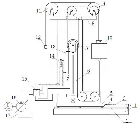
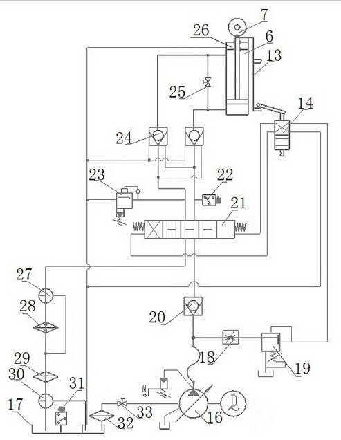
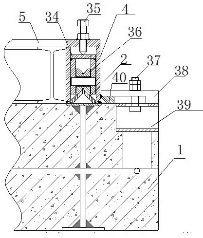
[0033] An adaptive continuous-phase hydraulic transmission pumping unit, such as figure 1 , figure 2 , image 3As shown, it comprises that the upper platform 8 is fixed on the base through a stand, and the vertical oil cylinder 6 is fixed on the base, and the movable pulley block 7 is connected to the end of the piston rod of the oil cylinder 6, and the upper and lower ropes connected by the rope tensioner pass through The fixed pulley 9 is connected to the balance box 10, and the transmission rope connected to the balance box 10 is connected to the rope hanger 12 matched with the oil well sucker rod through the rear pulley 11. The matched stroke controller 13, the adjustable base 5 is internally fitted with the roller box 34 installed through the lifting seat 4 which is evenly distributed on the left and right bottom frames, and the roller box 36 is matched with the corresponding ground angle steel guide rail 2, and is positioned on the left and right sides of the base pla...


PUM


Abstract

The invention discloses an adaptive continuous phase hydraulic transmission oil pumping machine. An adjustable base matches a ground angle steel rail, a lifting bolt is mounted on a platform of the base, an output pressure of a variable pump in a hydraulic circuit is connected to a combined control valve through a hose, a one-way valve, a hydraulic control reversing valve, a pressure reducing valve and an overflow valve are mounted on an integrated plate of the combined control valve, the hydraulic circuit is divided into two paths to be controlled through the combined control valve, a stop valve is mounted on a communicating pipe, a pressure relay is mounted on a main oil path leading to a rodless cavity of an oil cylinder, and the overflow valve is mounted on a main oil path leading to arod cavity of the oil cylinder. The machine is reasonable in structure, reliable in performance, convenient to operate and capable of meeting mining operation of various property reservoirs, in particular to thickened oil recovery operation, by means of a hydraulic control adaptive system, the situation that a sucker rod of an oil well changes along with a down stroke speed due to large viscosityof thickened oil is controlled, the acting time is saved, the energy-saving effect is good, the performance is safe and reliable, and the maintenance cost is low.

Description

technical field [0001] The invention relates to the field of oil production in oil fields, and belongs to a hydraulic transmission pumping unit, in particular to an adaptive continuous-phase hydraulic transmission pumping unit. Background technique [0002] The current oil extraction technology and surface oil extraction equipment in the oil field generally adopt the traditional beam pumping unit with mechanical transmission. However, its structure is huge and heavy, and it is difficult to adjust the stroke and adjust the balance. In order to improve efficiency, increase energy to underground oil reservoirs, such as water flooding; especially for the exploitation of heavy oil, in order to meet the working conditions of mechanical transmission pumping units, increase the fluidity of heavy oil through viscosity reduction, so steam injection and various Viscosity-reducing additives; in order to improve recovery, measures such as drilling infill wells and changing reservoir phy...

Claims


Application Information

Patent Timeline
IPC IPC(8): E21B43/00E21B15/00
CPCE21B43/121E21B15/003
Inventor 宋志亮邹波万文金
Owner 宋志亮
Learn More