A multi-cutter boring machine

A technology of roadheader and multi-cutter, applied in mining equipment, tunnels, earthwork drilling and other directions, can solve problems such as the inability to meet large-section tunnel excavation, expand the scope of geological application, improve excavation efficiency and effect, improve The effect of work efficiency

Active Publication Date: 2022-03-04
CHINA RAILWAY ENGINEERING EQUIPMENT GROUP CO LTD
View PDF11 Cites 0 Cited by
  • Summary
  • Abstract
  • Description
  • Claims
  • Application Information

AI Technical Summary

Problems solved by technology

[0006] In view of the deficiencies in the above-mentioned background technology, the present invention proposes a multi-cutter heading machine, which solves the technical problem that the existing road heading machine cannot meet the excavation requirements of large-section tunnels.

Method used


Image

  • A multi-cutter boring machine
  • A multi-cutter boring machine
  • A multi-cutter boring machine

Examples


Embodiment 1

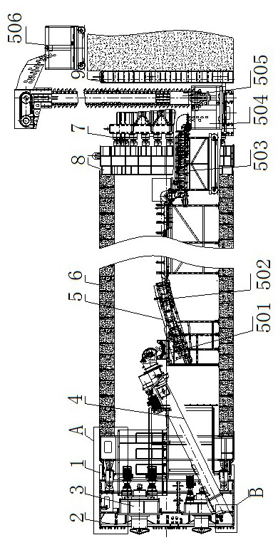
[0052] Example 1 A multi-cutter boring machine, such as figure 1 Shown, includes a housing body plays the role of a support, the front end of the housing body 1 is provided with a drive system 3, 3 are connected to the drive system mechanism 2 excavation, excavation mechanism 2 is provided with a slag system 4 and delivery system 5 muck . Rear of the housing body 1 is provided with a jacking system 7, 7 jacking system 8 passes through the top of the iron pipe section 6 of the housing into a fitting body. Under the pushing action of jacking system 7, the excavation of the tunnel face excavation mechanism 2 is implemented, by tapping System muck excavated muck conveyor 4 to conveyor system 5, and then by the transport system 5 muck the sediment discharge.

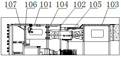
[0053] Specifically, such as figure 2 Shown, the outer shell 1 comprises a front section of the housing 101 are connected in sequence, the middle housing 102 and rear housing sections 103, 101 of the housing front section, a midd...

Embodiment 2

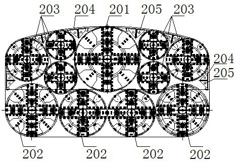
[0065] Example 2 A multi-cutter boring machine, such as Figure 7 Shown, the large and medium-sized cutter 201 as the cutter 202 plus panel type cutter spokes, the spokes plus cutter head panel and a panel comprising a radially disposed spokes. The cutter 203 is small spoke cutter, comprising a cutter spoke radially disposed spokes.

[0066] The large cutter 201, the cutter 202 medium-sized and small-sized cutter 203 are provided in the outer annular end of the outer beams are arranged in the circumferential direction tear knife 207 206, the ring 206 and the panel, great circle tear ring 206 on the knife blade as a gauge. 208 is provided with a hob, a doctor blade 209, cutter 201 large, medium, small cutter 202 and the center 203 of the cutter blade 210 provided with a central tail on the spoke.

[0067] Further, such as Figure 8 , The large cutter 201, 202 and small and medium-sized cutter behind the cutter 203 is provided with a stirring rod 211. Stirring rod 211 can be stirred t...


PUM


Abstract

The invention discloses a multi-cutter heading machine, which comprises an outer casing, a drive system is arranged at the front end of the outer casing, the drive system is connected with an excavation mechanism, and the excavation mechanism is equipped with a slag discharging system and a slag conveying system. The digging mechanism includes several cutterheads, each cutterhead is arranged side by side at the front end of the outer shell and forms a shape consistent with the cross-section of the outer shell in frontal projection, and the gap between each cutterhead and the gap between the cutterhead and the outer shell is an opening. Blind area is excavated, and a blind area conical plate is arranged on the outer shell opposite to the excavation blind area. The slag discharge system includes a blind area screw conveyor. The front end of the blind area screw conveyor is provided with a rock breaking structure opposite to the excavation blind area. The machine is connected with the muck conveying system. The invention can not only achieve the maximum effect of excavation and stirring, but also play a supporting role on the tunnel face and prevent collapse. At the same time, the scope of geological application of excavation equipment with a super-large rectangular section above 14 meters has been expanded.

Description

Technical field [0001] The present invention belongs to the technical field of sand and gravel layer tunneling, and more particularly to a multi-cutter boring machine. Background technique [0002] As urbanization continues to accelerate in the urban underground space construction project, the construction method of underground tunneling machinery become the trend. Among them, the rectangular tunnel boring machine because of its high utilization of space, suitable for shallow soil, relatively low construction costs and less impact on the surrounding environment more and more advantage of application. Currently rectangular tunnel boring machine is mainly used for subway entrance, Guojietongdao, beneath the two-lane roads and sidewalks, utility tunnel's construction, but the equipment used are 10 meters below the rank of rectangular cross-section. [0003] Currently tunnel section towards larger and wider direction, due to 14 meters above the level of the rectangular cross-section ...

Claims


Application Information

Patent Timeline
Patent Type & Authority Patents(China)
IPC IPC(8): E21D9/11E21D9/12E21D9/10
CPCE21D9/11E21D9/12E21D9/124E21D9/1093
Inventor 蒋鹏鹏龚廷民徐德帆孙英杰万国伟陈家浩袁征
Owner CHINA RAILWAY ENGINEERING EQUIPMENT GROUP CO LTD
Why Eureka
Try Eureka