Swing welding track planning method of welding robot

A welding robot and trajectory planning technology, applied in welding equipment, welding equipment, auxiliary welding equipment, etc., can solve the problems of limited swing range, increased difficulty of solving, and inapplicability, so as to ensure uniformity and reliability of welding performance, good versatility

Active Publication Date: 2020-12-01
NANJING ESTUN AUTOMATION CO LTD +1
View PDF6 Cites 3 Cited by
  • Summary
  • Abstract
  • Description
  • Claims
  • Application Information

AI Technical Summary

Problems solved by technology

However, this method solves the interpolation points in the space path according to the trajectory characteristics of the triangular pendulum, so it is only suitable for arc welding of the triangular pendulum, and cannot be applied to other swing forms such as sinusoidal pendulum and trapezoidal pendulum. There is a distance from the welding seam, on the one hand, the swing range will be limited, and on the other hand, the solder will not be fully filled, which will affect the firmness of the welding
In addition, because this method only determines the interpolation points at the swing amplitude, the controller needs to make the end of the robot pass through these points in the form of multiple linear motion instructions, without introducing speed planning, and it cannot guarantee that the robot has a relatively high speed during operation. good athletic performance
Chinese patent CN201810984979.9 discloses a space circular arc weaving welding interpolation method for an arc welding robot. This method adopts an "L" type weaving welding method to obtain a sinusoidal weaving trajectory that alternately swings on a cylindrical surface and a plane. The implementation method in the patent is based on the sine pendulum, which also belongs to a special type of weaving welding. When the type of weaving welding changes, the arc length calculation formula of the sine curve cannot be directly used, and the difficulty of solving increases accordingly, which is not universal. , and this method uses a large number of numerical calculation methods in the planning process, the calculation method and logic are relatively complicated, and the realizability in the actual application process is poor

Method used


Image

  • Swing welding track planning method of welding robot
  • Swing welding track planning method of welding robot
  • Swing welding track planning method of welding robot

Examples


Embodiment Construction

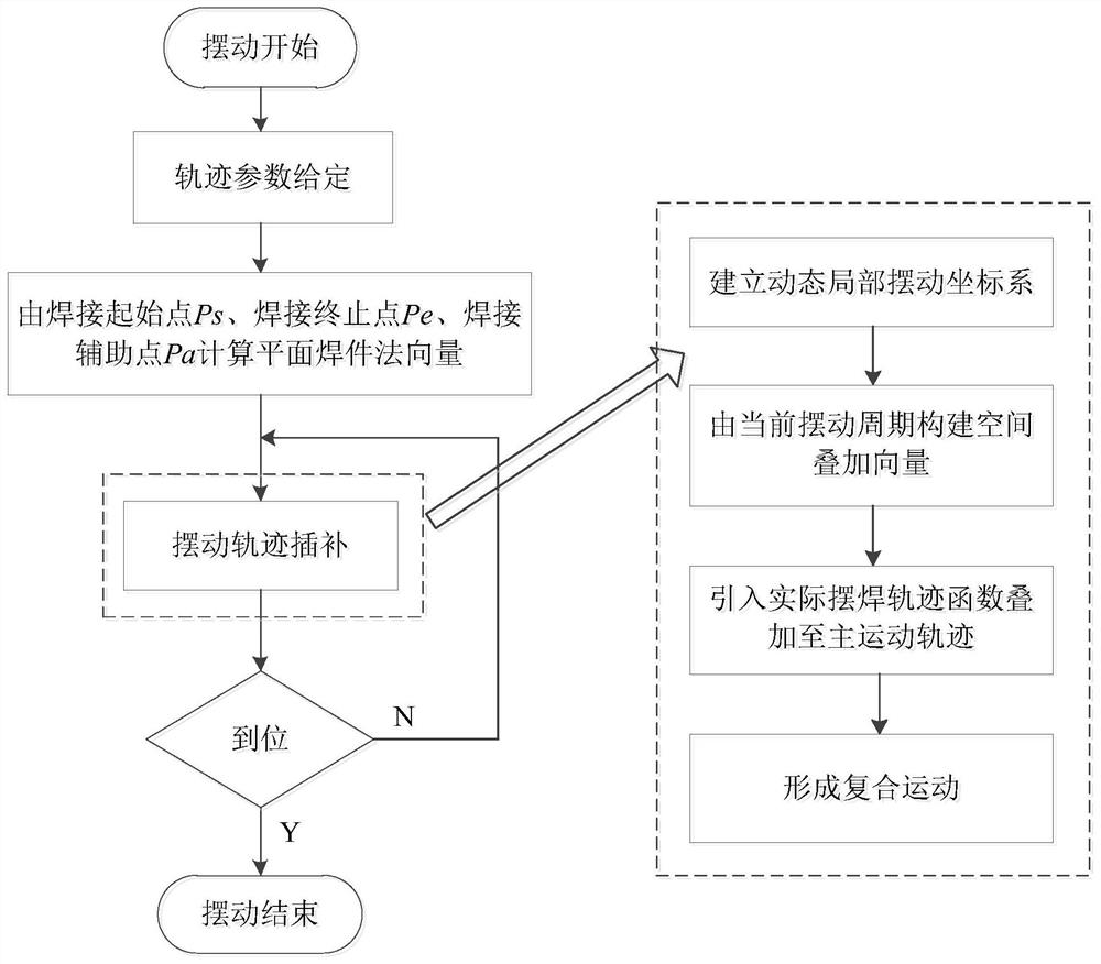
[0033] The content of the present invention will be further described in detail below in conjunction with specific embodiments.

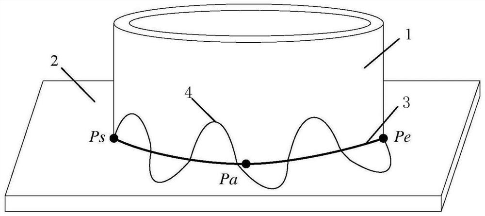
[0034] like figure 2 As shown, weldment 1 is a curved surface weldment, weldment 2 is a flat weldment, P s is the starting point of welding, P a is the welding auxiliary point, P e The three points are not collinear.

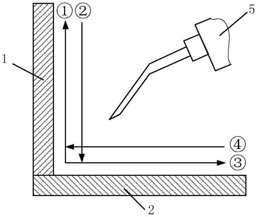
[0035] like image 3 As shown, in the section formed by the curved surface weldment (weldment 1) and the flat weldment (weldment 2), the welding gun 5 at the end of the robot reciprocates and alternately swings between the weldments in an "L"-shaped motion, as shown in the figure The serial number ①②③④ indicates the sequence of the weaving welding path. During the welding process, the welding torch is always attached to the surface of the weldment.

[0036] Since the robot controllers of most brands can realize the space arc trajectory interpolation, in this embodiment, the weldment 1 is a cylindrical weldment, and the weld curv...


PUM


Abstract

The invention discloses a swing welding track planning method of a welding robot. The swing welding track planning method can enable a welding gun at the tail end of the robot to perform alternate swing welding on the surface of a weldment in an L-shaped track by establishing a dynamic local swing coordinate system in real time and constructing a space superposition vector to form composite motionin the operation process of the robot. The method is simple and convenient in teaching operation, small in operand in a control system, simple in logic and easy to realize; a curve swing welding track formed by a space curved surface and a plane can be achieved, and good universality is achieved; the cross section of the final swing welding track is L-shaped, so that the welding gun can be attached to the surface of the weldment, and full filling of welding flux is realized; and a swing welding track displacement function in any form is supported and introduced in planning, the swing type presented by the displacement function supports flexible selection of a user according to actual welding requirements, the arithmetic logic of speed planning is supported, and the stability of movement of the robot in the welding operation process can be guaranteed.

Description

technical field [0001] The invention relates to a method for planning a weaving welding trajectory of a welding robot. Background technique [0002] Welding robots have been widely used in automated welding operations. The swing welding of welding robots means that the end tool of the robot is moving along the direction of the weld while continuously swinging at a set amplitude and frequency for welding, referred to as swing welding. In the welding operation, there is often a combination of curved surface weldment and flat weldment. At this time, the weld is curved, there is a certain angle between the weldment and the weldment, and there may even be a gap in the weld. In this case, the pendulum The welding trajectory movement can expand the actual welding range and achieve high-strength and high-efficiency welding effects, which has practical engineering significance. [0003] At present, there are relatively few studies on the planning method of arc swing trajectory for w...

Claims


Application Information

Patent Timeline
IPC IPC(8): B23K37/02B23K9/127B25J9/16
CPCB23K37/0252B23K9/12B25J9/1664
Inventor 赵臻晖
Owner NANJING ESTUN AUTOMATION CO LTD
Why Eureka
Try Eureka