Artificial heart valve

A technology of artificial heart valves and valve leaflets, which is applied in the field of medical devices, can solve problems such as difficulty in mitral valve interventional stent placement, insufficient physiological structure anastomosis, and difficult fixation, so as to achieve good anastomosis, less displacement, and less damage Effect

Pending Publication Date: 2020-12-04
QICHEN (SHANGHAI) MEDICAL EQUIP CO LTD
View PDF1 Cites 1 Cited by
  • Summary
  • Abstract
  • Description
  • Claims
  • Application Information

AI Technical Summary

Problems solved by technology

Although this technical solution can solve some technical problems in the manufacture of atrioventricular valve stents, due to the particularity of the mitral valve structure, it is difficult to insert the mitral valve interventional stent and it is not easy to fix after insertion, and there are still many pr

Method used


Image

  • Artificial heart valve
  • Artificial heart valve
  • Artificial heart valve

Examples


Embodiment 1

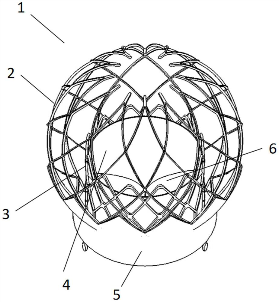
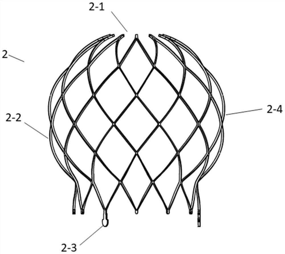
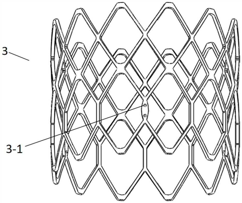
[0041]This embodiment provides an artificial heart valve, such as Figure 1-8 As shown, the artificial heart valve 1 includes a support, valve leaflets 6, suture film, sutures, and clips 7; the support includes an outer support 2, an inner support 3, and the outer support 2 is spherical to fit and support the atrium; the inner support 3 is Cylindrical, the inner stent 3 is set inside the outer stent 2; the leaflet 6 is set inside the inner stent 3 for replacing the original heart valve; the suture film is attached to the outer stent 2 and the inner stent 3; the inner stent 3 is provided with a suture The hole 3-1; the valve leaflet 6 passes through the suture hole 3-1 and the clip 7 is sutured with a suture thread.

[0042] like figure 1 As shown, the forming method of the outer frame 2 and the inner frame 3 includes one or more of metal material weaving, memory material cutting, laser cutting, and laser welding; the connection method of the outer frame 2 and the inner frame ...

Embodiment 2

[0066] A heart valve device provided in this embodiment is different from Embodiment 1 in that:

[0067] like Figure 10 As shown, the top of the outer stent 2 in this embodiment is a completely flat flat top 2-5 on the side close to the roof of the atrium.

[0068] In this embodiment, the side of the outer stent close to the roof of the atrium is completely flat and flat, so that the atrium is contracted to avoid atrial stenosis damage.

Embodiment 3

[0070] A heart valve device provided in this embodiment is different from Embodiments 1 and 2 in that:

[0071] like Figure 11 As shown, the top of the outer stent 2 in this embodiment is a concave top 2-6 on the side close to the roof of the atrium.

[0072] In this embodiment, the side of the outer stent close to the roof of the atrium is concave, so that the atrium is contracted to avoid damage from atrial stenosis.


PUM

PropertyMeasurementUnit
Wall thicknessaaaaaaaaaa
Diameteraaaaaaaaaa
Diameteraaaaaaaaaa

Abstract

The invention discloses an artificial heart valve. The artificial heart valve comprises a stent, valve leaflets, a suture membrane, suture lines and a clamping piece. The stent comprises an outer stent and an inner stent. The outer stent is spherical so as to be attached to and connected with the atrium in a supporting mode. The inner stent is cylindrical and is arranged inside the outer stent. The valve leaflets are arranged in the inner stent and used for replacing an original heart valve. The suture membrane is attached to the outer stent and the inner stent. Suture holes are formed in theinner stent. The valve leaflets penetrate through the suture holes and are sutured with the clamping piece through the suture lines. According to the artificial heart valve, a valve device can be fixed in the heart more stably and is not easy to shift; meanwhile, the valve is better matched with the physiological structure of the heart, so that perivalvular leakage is reduced; and damage of the valve to the ventricle and the subvalvular structure is reduced, the outer stent plays a role in protecting the inner stent and the valve leaflets, and the influence of compression of the inner stent and the valve leaflets by heart primary tissue on valve leaflet movement can be reduced. The service life of the artificial heart valve is prolonged.

Description

technical field [0001] The invention relates to the technical field of medical devices, in particular to an artificial heart valve. Background technique [0002] Heart valves are divided into atrioventricular valves (mitral valve, tricuspid valve) and semilunar valves (aortic valve, pulmonary valve) according to their corresponding shape and function. The tricuspid valve lies between the right atrium and right ventricle, the pulmonary valve lies between the right ventricle and the pulmonary artery, the mitral valve lies between the left atrium and left ventricle, and the mitral valve lies between the left ventricle and aorta aortic valve. From the cross-section of the heart, the aortic valve, mitral valve, and tricuspid valve are located in the middle, and the pulmonary valve is located anteriorly and slightly to the left of the aortic valve. The mitral annulus and tricuspid annulus are connected to each other, together with the membranous ventricular septum, they form the...

Claims


Application Information

Patent Timeline
IPC IPC(8): A61F2/24
CPCA61F2/24A61F2/2418A61F2220/0058A61F2220/0075
Inventor 梁玉晨
Owner QICHEN (SHANGHAI) MEDICAL EQUIP CO LTD
Why Eureka
Try Eureka