A step-by-step catalyst for waste coal gasification in fire areas and its preparation method

A catalyst, coal gasification technology, applied in the direction of catalyst activation/preparation, physical/chemical process catalysts, chemical instruments and methods, etc., can solve problems such as ineffective effects

Active Publication Date: 2021-04-30
CHINA UNIV OF MINING & TECH
View PDF6 Cites 0 Cited by
  • Summary
  • Abstract
  • Description
  • Claims
  • Application Information

AI Technical Summary

Problems solved by technology

These traditional catalysts used in coal catalytic gasification technology can significantly reduce the reaction temperature, increase the reaction speed, improve the gas composition, and increase the gas yield for conventional coal that has not been oxidized by high temperature. , The effect of abandoning coal in the fire area of ​​the coalfield where the physical and chemical properties have changed greatly has not been obvious

Method used


Image

  • A step-by-step catalyst for waste coal gasification in fire areas and its preparation method
  • A step-by-step catalyst for waste coal gasification in fire areas and its preparation method
  • A step-by-step catalyst for waste coal gasification in fire areas and its preparation method

Examples


Embodiment 1

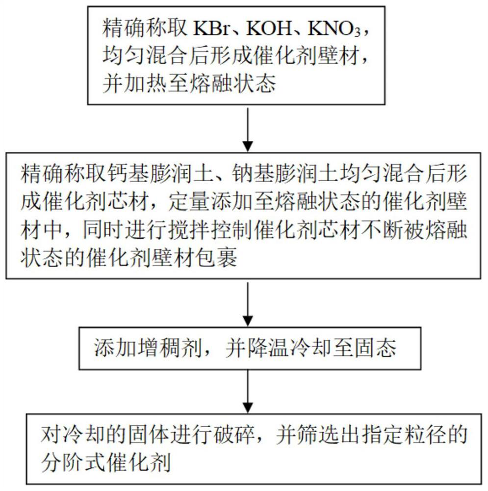
[0031] The catalyst core material selected in this embodiment is 21g calcium-based bentonite and 9g sodium-based bentonite; the selected catalyst wall material is 2.7g of KBr (melting point is about 510°C), 9.3g of KOH (melting point is about 380°C), 18g KNO 3(The melting point is about 334°C). The mass ratio of the catalyst core material and the catalyst wall material of the obtained hierarchical catalyst is 1:1. When the temperature exceeds 450°C, the catalyst wall material melts and ruptures to release the catalyst core material wrapped in it.

[0032] The graded catalyst that present embodiment is made carries out performance test, and result is as follows:

[0033] When the temperature of the prepared hierarchical catalyst rises to 450-480°C, the catalyst wall material begins to melt gradually. When the temperature exceeds 480°C, all the catalyst wall materials become molten, and the catalyst core material wrapped inside begins to melt. released to achieve the desired e...

Embodiment 2

[0044] The catalyst core material selected in this embodiment is 18g calcium-based bentonite and 12g sodium-based bentonite; the selected catalyst wall material is 2.4g of KBr (melting point is about 510°C), 12g of KOH (melting point is about 380°C), 15.6g KNO 3 (The melting point is about 334°C). The mass ratio of the catalyst core material to the catalyst wall material of the obtained hierarchical catalyst is 1:3.75. When the temperature exceeds 420°C, the catalyst wall material melts and ruptures to release the catalyst core material wrapped in it.

[0045] The graded catalyst that present embodiment is made carries out performance test, and result is as follows:

[0046] When the temperature of the prepared hierarchical catalyst rises to 400-450°C, the catalyst wall material begins to melt gradually. When the temperature exceeds 450°C, all the catalyst wall materials become melted, and the catalyst core material wrapped inside begins to melt. released to achieve the desi...

Embodiment 3

[0051] The catalyst core material selected in this embodiment is 19g calcium-based bentonite and 11g sodium-based bentonite; the selected catalyst wall material is 3g of KBr (the melting point is about 510°C), 12g of KOH (the melting point is about 380°C), and 15g of KNO 3 (The melting point is about 334°C). The mass ratio of the catalyst core material and the catalyst wall material of the obtained hierarchical catalyst is 1:2. When the temperature exceeds 480°C, the catalyst wall material melts and ruptures to release the catalyst core material wrapped in it.

[0052] The graded catalyst that present embodiment is made carries out performance test, and result is as follows:

[0053] When the temperature of the prepared step-by-step catalyst rises to 480-500°C, the catalyst wall material begins to melt gradually. When the temperature exceeds 500°C, all the catalyst wall materials become molten, and the catalyst core material wrapped inside begins to melt. released to achieve ...


PUM

PropertyMeasurementUnit
particle diameteraaaaaaaaaa
melting pointaaaaaaaaaa

Abstract

The invention discloses a step-by-step catalyst used for waste coal gasification in a fire area and a preparation method thereof. The step-by-step catalyst includes a catalyst core material and a catalyst wall material coated outside the catalyst core material; the catalyst core material consists of the following Composition of bentonite raw materials in weight percentage: 60-70% calcium-based bentonite, 30-40% sodium-based bentonite; catalyst wall material is 8-10% KBr, 30-40% KOH, 50-60% KNO 3 . The preparation raw materials of the hierarchical catalyst used in the waste coal gasification operation in the fire area are simple and easy to obtain, the price is cheap, green, safe and pollution-free, and the preparation process is simple. The wall material and the catalyst core material play a catalytic role in the early and late stages of gasification, realizing the efficient step-by-step catalytic gasification of the abandoned coal in the fire area, and can effectively re-gasify the abandoned coal in the fire area that has undergone oxidation deactivation in the fire area. Reduce a lot of waste of coal resources.

Description

technical field [0001] The invention relates to a catalyst for underground coal gasification and a preparation method thereof, in particular to a step-by-step catalyst for waste coal gasification in fire areas and a preparation method thereof, belonging to the technical field of coal resource development and utilization. Background technique [0002] Coalfield fires are common in major coal mining countries and regions such as the United States, India, South Africa, Australia, and Poland. According to statistics, more than 130 large and medium-sized mining areas in China's 25 major coal-producing provinces and regions have coal fire hazards to varying degrees. Among them, coal fires in Xinjiang are the most serious. The data shows that the loss of coal resources due to coal field fires is 4.2Gt, and the amount of coal resources directly burned by spontaneous combustion reaches 10-13.6Mt every year. It can be seen that although the coal directly burned by coal field fires on...

Claims


Application Information

Patent Timeline
Patent Type & Authority Patents(China)
IPC IPC(8): B01J27/25B01J35/02B01J37/02B01J37/00C10J3/00C10J3/20C10J3/48C10J3/72
CPCB01J27/25B01J35/026B01J37/0036B01J37/023C10J3/00C10J3/20C10J3/48C10J3/723C10J2300/093C10J2300/0986Y02P20/52
Inventor 戚绪尧陈良舟辛海会魏宏阳钦英杰
Owner CHINA UNIV OF MINING & TECH
Why Eureka
Try Eureka