
Continuous pyrolysis device

A pyrolysis and pyrolysis furnace technology, which is used in indirect heating dry distillation, special form dry distillation, petroleum industry, etc., can solve the problems of low pyrolysis efficiency and poor sealing, and achieves improved thermal efficiency, fast heating speed, and reduced operating costs. Effect

Pending Publication Date: 2020-12-11
河南省正源环境科技有限公司
View PDF3 Cites 1 Cited by
  • Summary
  • Abstract
  • Description
  • Claims
  • Application Information

AI Technical Summary

Problems solved by technology

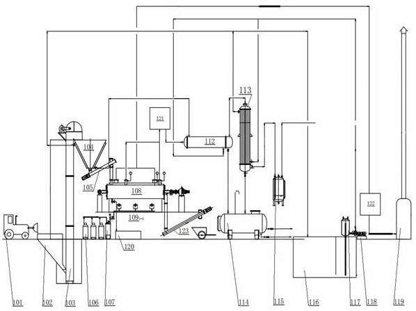
[0004] The current sludge pyrolysis device has the disadvantages of low pyrolysis efficiency and poor sealing, so it is necessary to design a continuous pyrolysis device, which has solved the problems existing in the existing sludge pyrolysis device

Method used


Image

  • Continuous pyrolysis device
  • Continuous pyrolysis device
  • Continuous pyrolysis device

Examples


Embodiment Construction

[0021] In order to make the technical problems, technical solutions and beneficial effects solved by the present application clearer, the present application will be further described in detail below in conjunction with the accompanying drawings and embodiments. It should be understood that the specific embodiments described here are only used to explain the present application, and are not intended to limit the present application.

[0022] In describing the present invention, it should be understood that the terms "center", "longitudinal", "transverse", "length", "width", "thickness", "upper", "lower", "front", " The orientation or positional relationship indicated by "rear", "left", "right", "vertical", "horizontal", "top", "bottom", "inner", "outer", etc. is based on the orientation shown in the drawings Or positional relationship is only for the convenience of describing the present invention and simplifying the description, but does not indicate or imply that the device ...


PUM


Abstract

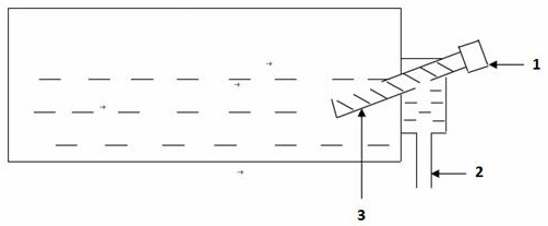
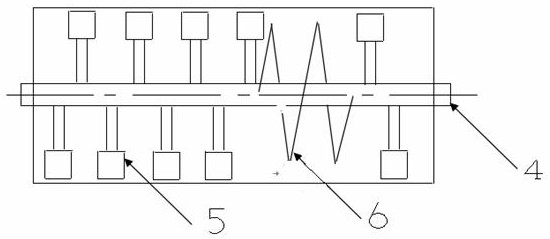
A mixture of sodium chloride and calcium chloride is added into a pyrolyzing furnace of the pyrolyzing device, the mixture becomes molten salt after being heated and melted, materials entering the pyrolyzing furnace are heated and decomposed, and due to the fact that the molten salt has the advantages of being large in density, high in heating speed, high in heat storage capacity and the like, thematerials can be pyrolyzed rapidly and fully; the rotary main shaft is arranged in the pyrolyzing furnace body, the main shaft structure can play a role in stirring and feeding by adopting a paddle and spiral combination mode, meanwhile, the top of the paddle is designed to be in a sharp tooth shape, materials bonded to the inner wall of the pyrolyzing furnace can be continuously swept off duringrotation, and heat transfer is prevented from being affected by serious coking. After the rotary main shaft pushes pyrolyzed materials to the discharging end of the pyrolyzing furnace, the discharging end of the pyrolyzing furnace is provided with an inclined small spiral conveyor, the lower end of the small spiral conveyor is inserted into molten salt, the materials accumulated at the discharging end can be smoothly pushed out of the pyrolyzing furnace and then fall into a discharging pipe, and therefore discharging in a sealed state is achieved.

Description

technical field [0001] The invention relates to a continuous pyrolysis device, which belongs to the design and application field of waste treatment devices. Background technique [0002] At present, various organic solid wastes such as oil sludge, urban sludge, waste plastics, waste rubber, and distillation residues are mainly treated in China by means of mechanical dehydration, thermal drying, aerobic fermentation, anaerobic digestion, and dry incineration. At present, in the sludge harmless treatment projects, the proportion of drying treatment still ranks first, and the proportion of mechanical deep dehydration is higher than that of energy drying treatment. [0003] More than half of the landfills in the country are already in overload operation, and the disposal method of sludge landfill will be hindered as the number of full-capacity landfills increases. Under the background of the ecological cycle, the road to resource utilization is gradually By the industry's atten...

Claims


Application Information

Patent Timeline
IPC IPC(8): C10B53/00C10B47/44
CPCC10B53/00C10B47/44
Inventor 王协力赵宗凯
Owner 河南省正源环境科技有限公司
Learn More