Brake pump direct-drive permanent magnet motor

A permanent magnet motor and motor technology, which is applied to synchronous motors with static armatures and rotating magnets, electric components, magnetic circuit rotating parts, etc., can solve the problems of large motor size, improve performance and reduce production costs. , The effect of reducing the difficulty of production and processing

Inactive Publication Date: 2020-12-11
YINCHUAN WEILI REDUCER MACHINERY
View PDF4 Cites 2 Cited by
  • Summary
  • Abstract
  • Description
  • Claims
  • Application Information

AI Technical Summary

Problems solved by technology

However, the motor has the

Method used


Image

  • Brake pump direct-drive permanent magnet motor
  • Brake pump direct-drive permanent magnet motor
  • Brake pump direct-drive permanent magnet motor

Examples


Embodiment Construction

[0020] The following examples are further explanations and supplements to the present invention, and do not constitute any limitation to the present invention.

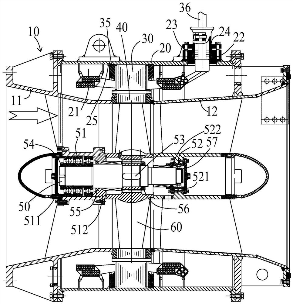
[0021] refer to figure 1 , the pump gate direct drive permanent magnet motor of the present invention includes a connection base 10, a casing 20, a stator assembly 30, a rotor assembly 40, a main shaft 50 and an impeller 60, the motor is used in an integrated pump and gate device, and it drives the impeller 60 Rotate to realize water retention and prevent backflow of outer rivers, and can also pump water from low places to high places to realize strong drainage.

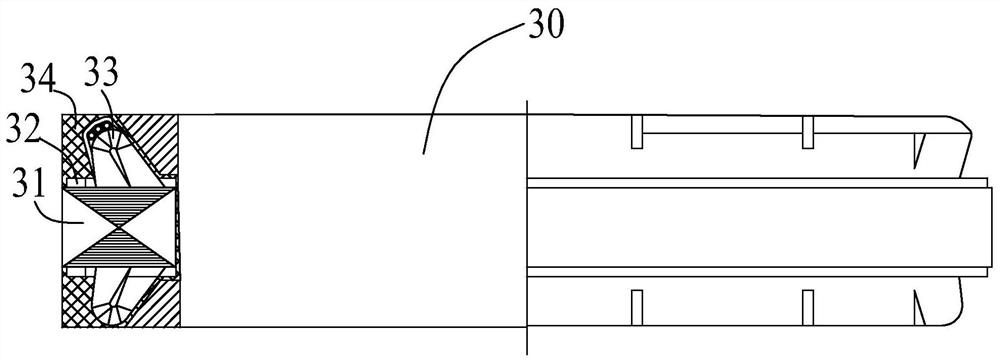
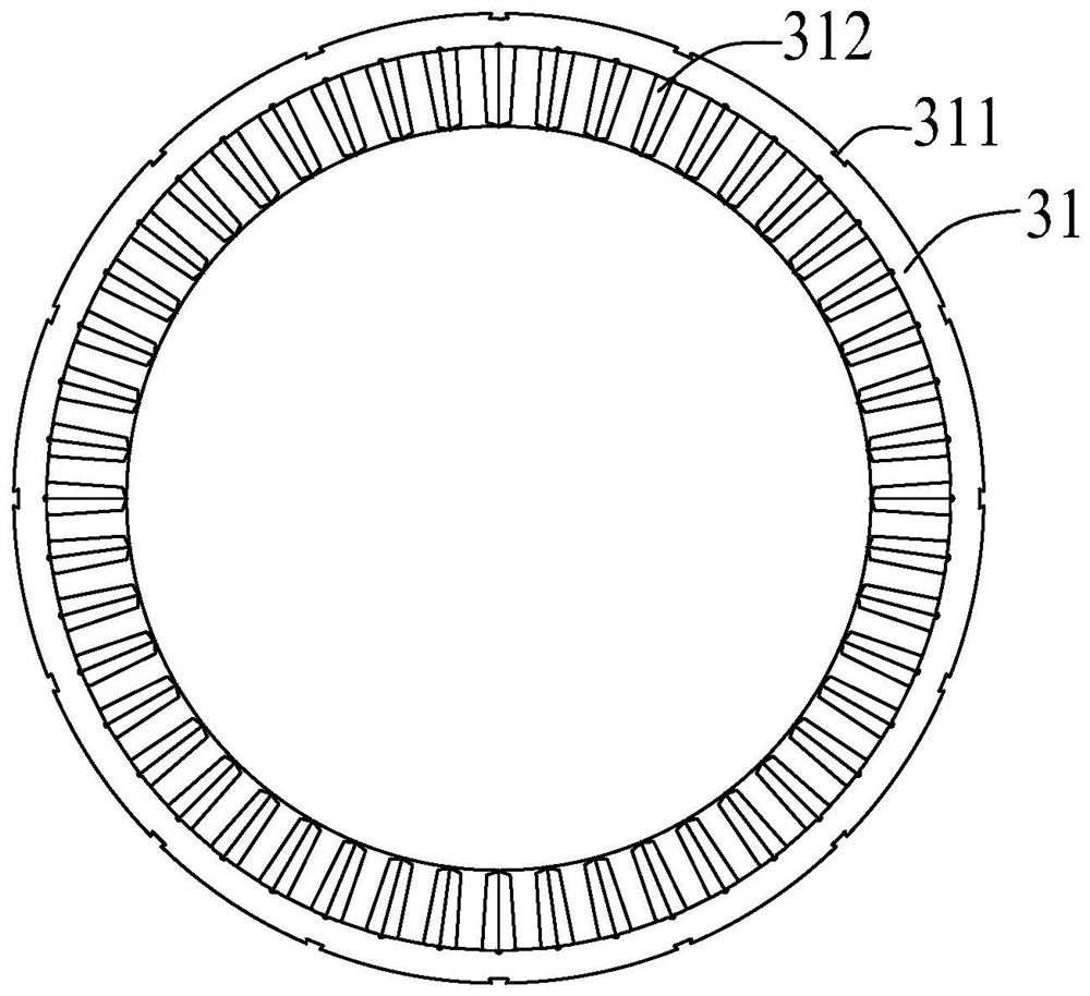
[0022] Such as figure 1 , figure 2 and image 3 As shown, the stator assembly 30 includes a stator punch 31 , a stator pressure ring 32 , a stator coil 33 , a stator potting 34 , a stator end plate 35 and a lead wire 36 . Among them, there are multiple stator punches 31, the number of which is determined according to the design requirements of the stato...


PUM


Abstract

The invention relates to a brake pump direct-drive permanent magnet motor, which comprises a casing and connecting seats mounted at two ends of the casing, each connecting seat consists of an upper connecting seat and a lower connecting seat, a rotor component is arranged between each upper connecting seat and the corresponding lower connecting seat, a stator component is arranged on the outer side of each rotor component, and sealant is filled between each stator component and the casing. An impeller used for blocking water or draining water is arranged in the rotor assembly, and the impelleris fixedly connected with a main shaft arranged in the middle of the connecting seat. After the motor is started, a rotating magnetic field is generated between the stator assembly and the rotor assembly, the magnetic field forms driving torque, and therefore the rotor assembly is driven to rotate around the axis of the main shaft, and the impeller is driven to rotate around the axis of the mainshaft to achieve water blocking or water draining of a gate pump. According to the invention, the stator assembly is hermetically connected with the casing, and the motor has the characteristics of low production and processing difficulty, low cost, high motor reliability, good heat dissipation effect, small motor size and the like.

Description

【Technical field】 [0001] The invention relates to the field of motors, in particular to a gate pump direct-drive permanent magnet motor with simple processing, strong reliability and low cost. 【Background technique】 [0002] The current sluice pump system is mainly used for electromechanical drainage and irrigation, flood control and drainage, or low-lift and large-flow water intake projects combined with drainage and irrigation through submersible electric pump devices. Most of the existing submersible electric pump devices are full-through-flow submersible electric pumps, and their submersible motors adopt a wet stator winding structure, and the coils of the wet stator winding structure are special water-resistant windings manufactured by using the patented multi-layer eutectic co-extrusion winding wire technology The impeller of the water pump is placed in the inner cavity of the motor rotor, and the blades of the impeller are welded into a whole with the inner circle of ...

Claims


Application Information

Patent Timeline
IPC IPC(8): H02K9/197H02K5/22H02K5/04H02K1/27H02K1/16H02K21/14H02K7/14
CPCH02K9/197H02K5/22H02K5/04H02K1/2773H02K1/165H02K21/14H02K7/14H02K2213/03
Inventor 董强亮孙宏凯
Owner YINCHUAN WEILI REDUCER MACHINERY
Why Eureka
Try Eureka