Cone beam CT and image fusion combined cervical vertebra in-vivo three-dimensional motion analysis method

A technology of image fusion and analysis method, which is applied in the field of analysis of the three-dimensional movement of the cervical spine, can solve the problems of large radiation dose, unclear imaging, and inability to truly reflect the human cervical spine, and achieve the effect of low radiation dose and high speed

Active Publication Date: 2020-12-15
南昌大学第一附属医院
View PDF13 Cites 1 Cited by
  • Summary
  • Abstract
  • Description
  • Claims
  • Application Information

AI Technical Summary

Problems solved by technology

[0003] In order to solve the problem of routine X-ray fluoroscopy shooting, what is obtained is a two-dimensional static position, and C1 is blocked by the skull, and C7 is blocked by the clavicle, and the image is not clear; while MRI or CT can be used to see the 3D static structure, but cannot see Dynamic movement abnormalities, and these two scans are usually in the supine position, non-weight-bearing, and cannot truly reflect the function of the human cervical spine; MRI also has a long scan time, and 3D modeling is inconvenient; CT also has problems such as large radiation doses, the purpose of the present invention It provides a method for analyzing the three-dimensional motion of the cervical spine in vivo combined with cone-beam CT and image fusion

Method used


Image

  • Cone beam CT and image fusion combined cervical vertebra in-vivo three-dimensional motion analysis method
  • Cone beam CT and image fusion combined cervical vertebra in-vivo three-dimensional motion analysis method
  • Cone beam CT and image fusion combined cervical vertebra in-vivo three-dimensional motion analysis method

Examples


Embodiment Construction

[0025] The implementation of the present invention will be illustrated by specific specific examples below, and those skilled in the art can easily understand other advantages and effects of the present invention from the contents disclosed in this specification.

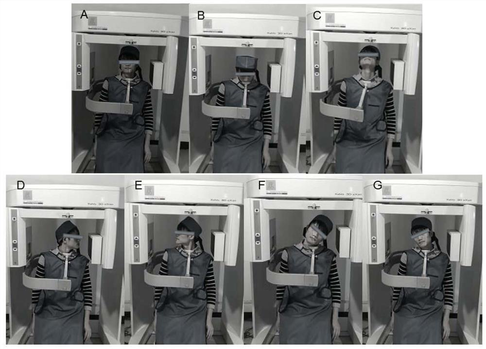
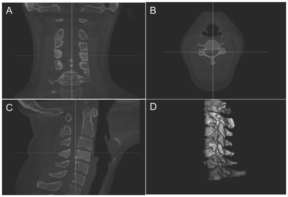
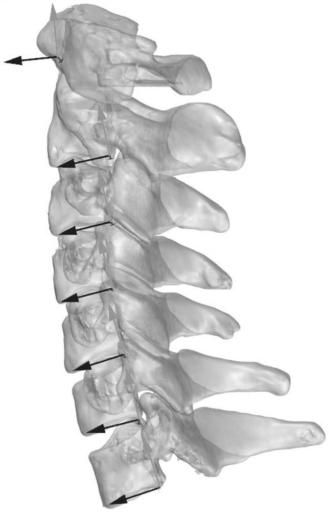
[0026] see Figure 1 to Figure 5 . It should be noted that the structures, proportions, sizes, etc. shown in the drawings attached to this specification are only used to match the content disclosed in the specification, for those who are familiar with this technology to understand and read, and are not used to limit the implementation of the present invention. Limiting conditions, so there is no technical substantive meaning, any modification of structure, change of proportional relationship or adjustment of size, without affecting the effect and purpose of the present invention, should still fall within the scope of the present invention. The disclosed technical content must be within the scope covered. At the sa...


PUM


Abstract

The invention discloses a cone beam CT and image fusion combined cervical vertebra in-vivo three-dimensional motion analysis method. The method comprises the following steps of S1, enabling a cone beam CT machine to shoot images of different cervical vertebra function positions; S2, importing to carry out image segmentation and 3D modeling; S3, for the 3D cervical vertebra model at the neutral position, determining a local coordinate system according to the anatomical orientation of the human body; S4, performing image fusion and recording spatial position parameter change on each segment of cervical vertebra model at different functional positions relative to the neutral position; S5, performing threshold judgment on the precision of image fusion to determine whether the image fusion is successful or not; and S6, further calculating the spatial position parameter change between different sections to obtain the relative change of the two sections, and the invention relates to the technical field of CT influence. According to the invention, the problem of unclear imaging caused by conventional X-ray fluoroscopy shooting is solved; nuclear magnetic resonance (MRI) or computed tomography (CT) is adopted, so that dynamic motion abnormity cannot be seen; MRI is long in scanning time and inconvenient in 3D modeling; and CT also has the problems of large radiation dose and the like.

Description

technical field [0001] The invention relates to the technical field of CT influence, in particular to a method for analyzing the three-dimensional movement of the cervical spine in vivo by combining cone-beam CT and image fusion. Background technique [0002] The cervical spine is divided into seven segments C1 to C7. The rotation, flexion and extension of the human head are all achieved by the compound movements of these segments. The abnormal spatial position (such as straightening, loss of curvature) and abnormal movement of these segments are important factors in the diagnosis, treatment and efficacy evaluation of clinically relevant diseases. X-rays are routinely used for fluoroscopic photography, and the two-dimensional static position is obtained, and C1 is blocked by the skull, and C7 is not clearly imaged by the clavicle. However, nuclear magnetic resonance MRI or CT can see 3D static structures, but cannot see dynamic abnormalities, and these two scans are usuall...

Claims


Application Information

Patent Timeline
Patent Type & Authority Applications(China)
IPC IPC(8): G06T17/00G06T7/55G06T7/73G06T7/246
CPCG06T17/00G06T7/55G06T7/73G06T7/246G06T2207/10081G06T2207/20221G06T2207/30008Y02T10/40
Inventor 万宗淼王少白
Owner 南昌大学第一附属医院
Why Eureka
Try Eureka