Fuel cell flow field plate and fuel cell

A fuel cell and flow field plate technology, which is applied to fuel cells, fuel cell components, circuits, etc., can solve the problems of uneven gas distribution, low electrode surface utilization rate, low reaction gas flow rate, etc., and achieves increased convective conversion Thermal area, reduced assembly workload, and uniform temperature field distribution

Pending Publication Date: 2020-12-15
SHANGHAI JIAO TONG UNIV
View PDF0 Cites 2 Cited by
  • Summary
  • Abstract
  • Description
  • Claims
  • Application Information

AI Technical Summary

Problems solved by technology

The water management problem of fuel cells has always been a key issue in the performance optimization of fuel cells. When the stack is working at a large current density, it is prone to "water flooding", which hinders the reaction gas from reaching the active site, thereby improving the performance of the fuel cell. greatly decreased
Although the pressure loss of the parallel flow channel is small, it is easy to cause uneven gas distribution; although the serpentine flow channel has a strong drainage capacity, but the flow channel is too long, causing the pressure drop of the reaction gas to be too large. Prone to insufficient reactive gas supply and "flooding"
Due to the discontinuity of the flow channel, the gas is forced to pass through the gas diffusion layer, which improves the utilization rate of the gas, but the fluid distribution is uneven and the pressure drop is large
Point flow channels have problems such as easy short circuit, low electrode surface utilization, and low reaction gas flow rate.
Although the mesh flow channel strengthens the mass transfer process, due to the low gas flow rate in the flow channel, the drainage capacity is poor, and the flow uniformity is not ideal

Method used


Image

  • Fuel cell flow field plate and fuel cell
  • Fuel cell flow field plate and fuel cell
  • Fuel cell flow field plate and fuel cell

Examples


Embodiment 1

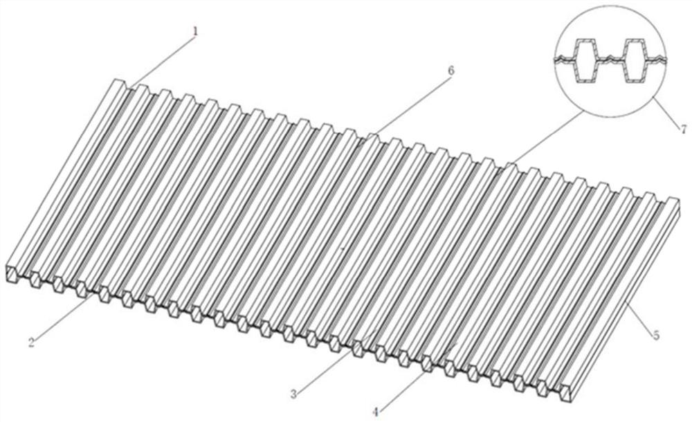
[0033] like figure 1 As shown, a fuel cell flow field plate provided by the present invention is mainly suitable for hydrogen-air fuel cells and hydrogen-oxygen fuel cells, the flow field plate is made of metal material, the cathode plate includes an air inlet, Gas outlet, flow channel, ridge, groove at the bottom of the flow channel groove, the anode plate includes air inlet, gas outlet, flow channel, ridge, and boss at the bottom of the flow channel groove. The air inlet and the air outlet are connected through flow channels on the flow field plate. The flow channel adopts parallel flow channel, the cross section of the flow channel adopts trapezoidal cross section, and the groove and boss at the bottom of the flow channel are triangular. When the battery is assembled, the groove of the cathode plate and the boss of the anode plate cooperate with each other to fix the two plates so that they cannot move. When the flow field plate of the present invention is in operation, t...

Embodiment 2

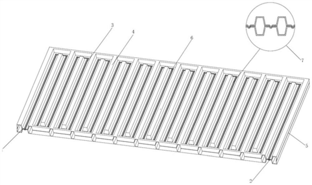
[0035] like figure 2 As shown, a fuel cell flow field plate provided by the present invention is mainly suitable for hydrogen-air fuel cells and hydrogen-oxygen fuel cells, the flow field plate is made of metal material, the cathode plate includes an air inlet, Gas outlet, flow channel, ridge, groove at the bottom of the flow channel groove, the anode plate includes air inlet, gas outlet, flow channel, ridge, and boss at the bottom of the flow channel groove. The air inlet and the air outlet are connected through flow channels on the flow field plate. The flow channel adopts a serpentine flow channel, the cross section of the flow channel adopts a trapezoidal cross section, and the groove and the boss at the bottom of the flow channel are arc-shaped. When the battery is assembled, the groove of the cathode plate and the boss of the anode plate cooperate with each other to fix the two plates so that they cannot move. When the flow field plate of the present invention is in o...

Embodiment 3

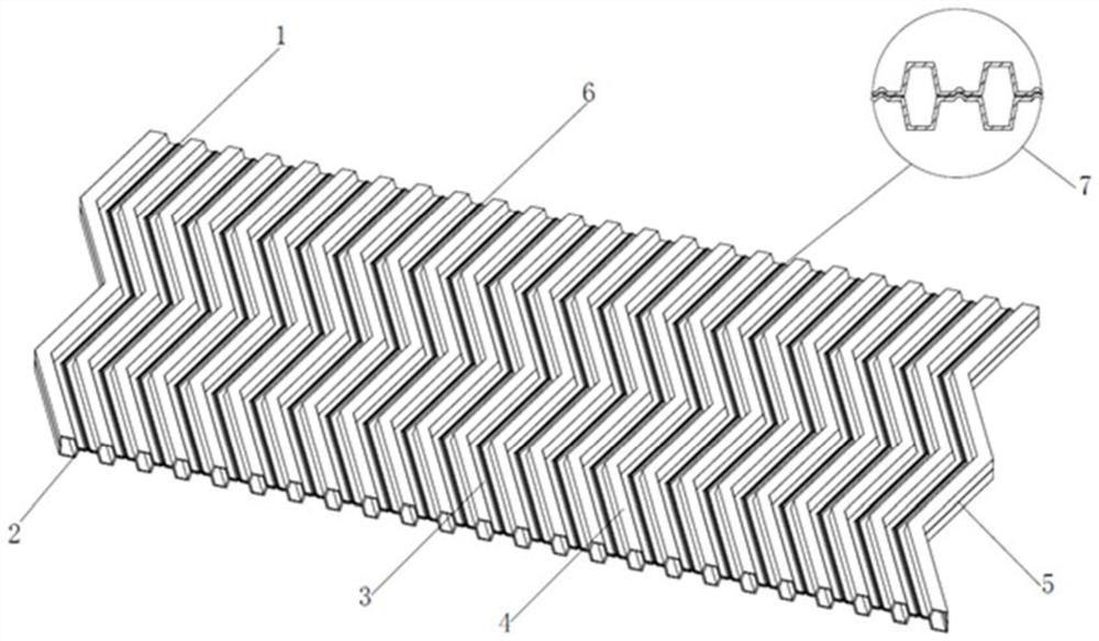
[0037] like image 3 As shown, a fuel cell flow field plate provided by the present invention is mainly suitable for hydrogen-air fuel cells and hydrogen-oxygen fuel cells, the flow field plate is made of metal material, the cathode plate includes an air inlet, Gas outlet, flow channel, ridge, groove at the bottom of the flow channel groove, the anode plate includes air inlet, gas outlet, flow channel, ridge, and boss at the bottom of the flow channel groove. The air inlet and the air outlet are connected through flow channels on the flow field plate. The flow channel adopts a folded flow channel, the cross section of the flow channel adopts a trapezoidal cross section, and the groove and the boss at the bottom of the flow channel are trapezoidal. When the battery is assembled, the groove of the cathode plate and the boss of the anode plate cooperate with each other to fix the two plates so that they cannot move. When the flow field plate of the present invention is in opera...


PUM


Abstract

The invention provides a fuel cell flow field plate and a fuel cell, relates to the field of fuel cells, and is mainly suitable for hydrogen-air fuel cells and hydrogen-oxygen fuel cells. The flow field plate comprises an air inlet, an air outlet, a flow channel, a ridge, a groove and a boss, wherein the groove and the boss are formed in the bottom of the flow channel, are distributed at the bottom of a flow channel ditch along the flow channel direction and are respectively positioned on two polar plates. According to the flow field plate, the grooves and the bosses are arranged on the wall surfaces of the bottoms of the flow channels of the two polar plates respectively, and when the fuel cell is assembled, the grooves and the bosses are meshed with each other, so that the two polar plates cannot move relatively. The groove and boss structures in the flow channels divide the interface of the liquid drop and the wall of the flow channel, so that the effective contact area of the liquid drop and the wall of the flow channel is reduced, liquid water is prevented from forming a continuous water film, the discharge of the liquid water is facilitated, and the flooding phenomenon is relieved. And meanwhile, due to the existence of the groove and boss structures, airflow disturbance is further enhanced, the convective heat exchange area is increased, and the mass transfer and heat exchange capacity of a flow field is improved.

Description

technical field [0001] The invention relates to the field of fuel cells, in particular to a fuel cell flow field plate and a fuel cell. Background technique [0002] Hydrogen-air fuel cell is a promising new power generation device. It uses hydrogen as reducing agent and oxygen as oxidizing agent to realize the direct conversion of chemical energy to electrical energy through chemical reaction. Fuel cells do not need to follow the limit of the thermal efficiency of the Carnot cycle and can achieve high theoretical efficiencies. In addition, the fuel cell also has the advantages of low noise, environmental protection, low operating temperature, and fast start-up. Therefore, hydrogen-air fuel cells have received extensive attention. The water management problem of fuel cells has always been a key issue in the performance optimization of fuel cells. When the stack is working at a large current density, it is prone to "water flooding", which hinders the reaction gas from reach...

Claims


Application Information

Patent Timeline
Patent Type & Authority Applications(China)
IPC IPC(8): H01M8/0258H01M8/026H01M8/0263H01M8/0206H01M8/0213
CPCH01M8/0206H01M8/0213H01M8/0258H01M8/026H01M8/0263Y02E60/50
Inventor 侯俊波章俊良高骞柯长春
Owner SHANGHAI JIAO TONG UNIV
Why Eureka
Try Eureka