Hydrostatic bearing and hydrostatic guide rail assembly

A technology of hydrostatic bearing and hydrostatic guide rail, applied in the directions of hydrostatic bearing, bearing, shaft and bearing, etc., can solve the problems of short life, high cost, difficult realization, etc., and achieve the effect of simple structure and low manufacturing cost.

Active Publication Date: 2020-12-18
HUAZHONG UNIV OF SCI & TECH
View PDF5 Cites 6 Cited by
  • Summary
  • Abstract
  • Description
  • Claims
  • Application Information

AI Technical Summary

Problems solved by technology

Under extreme processing conditions such as ultra-precision heavy-duty hard turning and hard milling, the dynamic performance of hydrostatic bearings under strong disturbances such as cutting forces cannot meet processing requirements
[0004] Therefore, in order to improve the rigidity of the hydrostatic bearing, a variety of optimization schemes have been proposed, such as the use of a diaphragm throttle, so as to achieve passive compensation of the oil film pressure and improve the stiffness at the same time, but the compensation time delay is relatively long. And it is difficult to accurately control, short life, and high cost; or a piezoelectric actuator is installed on the oil sealing side to actively compensate the oil film according to pressure feedback, but the control algorithm of this scheme is complicated and difficult to implement; or in the oil Adding magnetic materials makes the fluid exhibit special properties under a magnetic field to improve the supporting performance of the oil film, but it also has problems such as difficulty in precise control

Method used


Image

  • Hydrostatic bearing and hydrostatic guide rail assembly
  • Hydrostatic bearing and hydrostatic guide rail assembly
  • Hydrostatic bearing and hydrostatic guide rail assembly

Examples


Embodiment 1

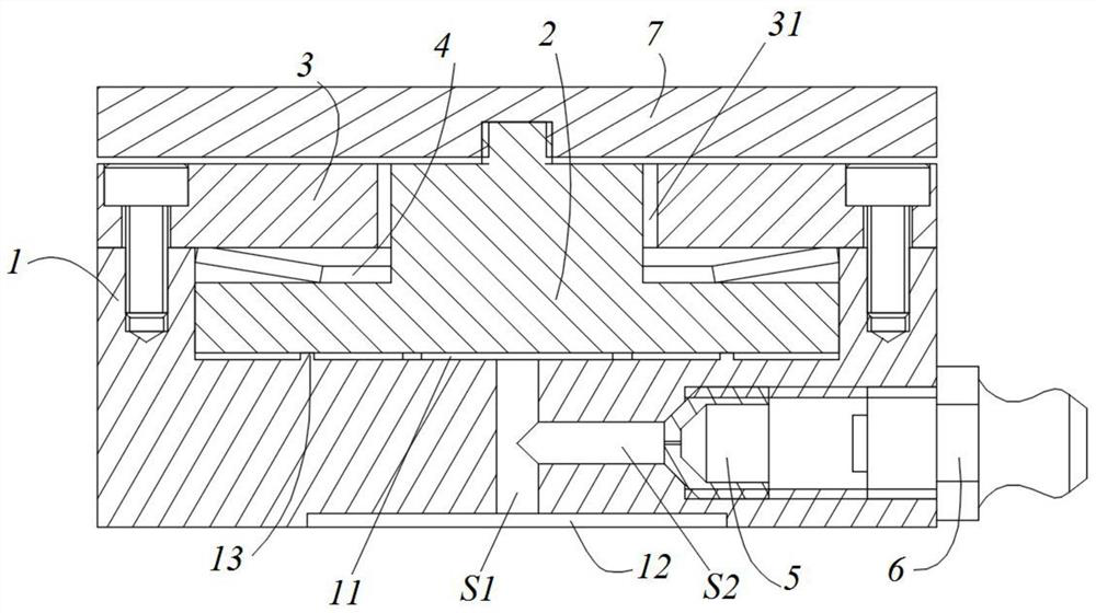
[0031] like figure 1 As shown, the hydrostatic bearing in this embodiment includes:

[0032] The support block 1 has a sub-chamber 11 on its upper part and a main chamber 12 on its lower part, and the sub-chamber 11 and the main chamber 12 are communicated through the first channel S1. Further, the main chamber 12 The depth is 1-3 mm (preferably 2 mm), and at least one limiting boss 13 is provided at the bottom of the sub-chamber S1. In this embodiment, the limiting boss 13 and the support block 1 can be integrally formed. And the height of the stop protrusion 13 is 0.2-1.0mm, preferably 0.5mm; meanwhile, the diameter of the secondary chamber 11 is 20-35mm (preferably 25mm), and the diameter of the main chamber 12 is 10-25mm ( preferably 15 mm);

[0033] A cover plate 3, which is set on the support block 1, and is detachably connected to the support block 1 by bolts, etc., and the cover plate 3 is provided with an opening communicating with the secondary chamber S1 31;

[...

Embodiment 2

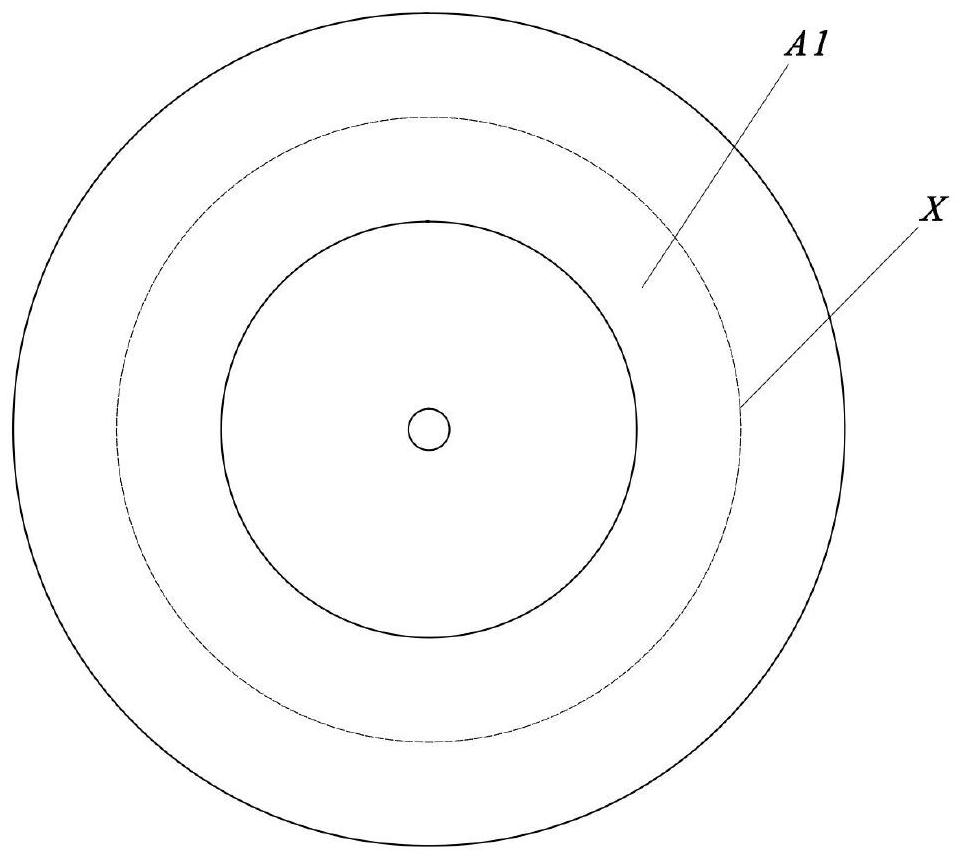
[0045] The only difference between this embodiment and Embodiment 1 is that in this embodiment, the bottom area of ​​the auxiliary chamber 11 is 5-10% (preferably 6-8%, preferably 6-8%) larger than the effective bearing area of ​​the bottom surface of the support block 1. Particularly preferred is 6.5%).

[0046] like image 3 As shown, the effective bearing area of ​​the bottom surface of the support block 1 is the area of ​​the area A1 surrounded by the center line X of the oil sealing surface, and the force of the oil film acting on the bottom surface of the support block 1 is mainly the oil pressure in the chamber 12 and the effective load bearing area. The product of the area. Because the bottom area of ​​the auxiliary chamber 11 is 5-10% larger than the effective bearing area of ​​the bottom surface of the support block 1, and the main chamber 12 communicates with the oil pressure in the auxiliary chamber 11, so that the internal oil pressure of the hydrostatic bearing ...

Embodiment 3

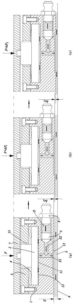
[0049] This embodiment provides a static pressure rail assembly, such as Figure 4 As shown, it includes: guide rail 21, slide plate 8, pressure gauge 9, regulating valve 10, hydraulic pump 20 and the hydrostatic bearing described in Embodiment 1 or 2;

[0050] Wherein, the slide plate 8 is connected to the bearing disc 7, the guide rail 21 is in clearance fit with the bottom surface of the support block 1, and the high-pressure oil in the external oil supply equipment flows into the restrictor 5 through the adapter 6, and then passes through the restrictor. The flow device 5 is throttled so that the pressure of the high-pressure oil is reduced to become low-pressure oil, and the low-pressure oil fills the entire main chamber 12 and the auxiliary chamber 11 through the second channel S2 and the first channel S1, and the oil on the bottom surface of the support block 1 An oil film is formed between the guide rail 10 to support the upper slide 8.

[0051] Further, the hydraulic...


PUM


Abstract

The invention discloses a hydrostatic bearing and a hydrostatic guide rail assembly. The hydrostatic bearing comprises a supporting block, a cover plate, a bearing piston, a bearing disc, an elastic element and a throttler, wherein an auxiliary cavity is formed in the upper portion of the supporting block, a main cavity is formed in the lower portion of the supporting block, and the auxiliary cavity communicates with the main cavity; the cover plate covers the supporting block and is provided with an open hole communicating with the auxiliary cavity; the bearing piston is contained in the auxiliary cavity; the bearing disc is connected with the top of the bearing piston extending out of the open hole and used for bearing external loads; the elastic element is arranged in the auxiliary cavity, one end of the elastic element abuts against the bearing piston, and the other end of the elastic element abuts against the bottom face of the cover plate; and the throttler is installed in the supporting block, an outlet of the throttler communicates with a first channel through a second channel, and an inlet of the throttler communicates with external oil supply equipment. According to the hydrostatic bearing and the hydrostatic guide rail assembly, small hole throttling is combined with a piston type displacement self-compensation structure, so that when the bearing force borne by the hydrostatic bearing changes, rapid response can be achieved, the hydrostatic bearing can return to the original position within a short time, and then quasi-infinite rigidity is achieved.

Description

technical field [0001] The invention relates to the field of static pressure technology, in particular to a static pressure bearing and a static pressure guide rail assembly. Background technique [0002] Hydrostatic thrust bearings have been widely used in high-speed, heavy-duty, ultra-precision machine tool guide rails and spindles due to their superior performance of high bearing capacity, high stiffness, and high damping. Its stiffness coefficient has always been one of the important parameters for evaluating the dynamic performance of machine tools. one. [0003] As machine tools continue to develop towards high precision, hydrostatic bearing technology is also facing new challenges. Under extreme processing conditions such as ultra-precision heavy-duty hard turning and hard milling, the dynamic performance of hydrostatic bearings cannot meet the processing requirements under strong disturbances such as cutting forces. [0004] Therefore, in order to improve the rigid...

Claims


Application Information

Patent Timeline
Patent Type & Authority Applications(China)
IPC IPC(8): F16C32/06
CPCF16C32/0648F16C32/0655F16C32/067
Inventor 黄禹荣佑民吴昊李宇恒陈春梦
Owner HUAZHONG UNIV OF SCI & TECH
Why Eureka
Try Eureka