Efficient liquefaction system of regenerative refrigerator adopting direct currents

A regenerative and refrigerator technology, applied in refrigeration and liquefaction, refrigerators, refrigeration components, etc., can solve the problems of high cost of helium collection and liquefaction, high cost of helium liquefaction, and large heat transfer resistance. Achieve the effect of small heat transfer resistance, improve liquefaction capacity and reduce thermal resistance

Pending Publication Date: 2020-12-18
TONGJI UNIV
View PDF0 Cites 5 Cited by
  • Summary
  • Abstract
  • Description
  • Claims
  • Application Information

AI Technical Summary

Problems solved by technology

[0004] The cost of helium collection and liquefaction is high. There are also some small mobile helium liquefaction devices on the market. Usually, the liquefaction flow channel is wound ...

Method used


Image

  • Efficient liquefaction system of regenerative refrigerator adopting direct currents
  • Efficient liquefaction system of regenerative refrigerator adopting direct currents
  • Efficient liquefaction system of regenerative refrigerator adopting direct currents

Examples


Embodiment 1

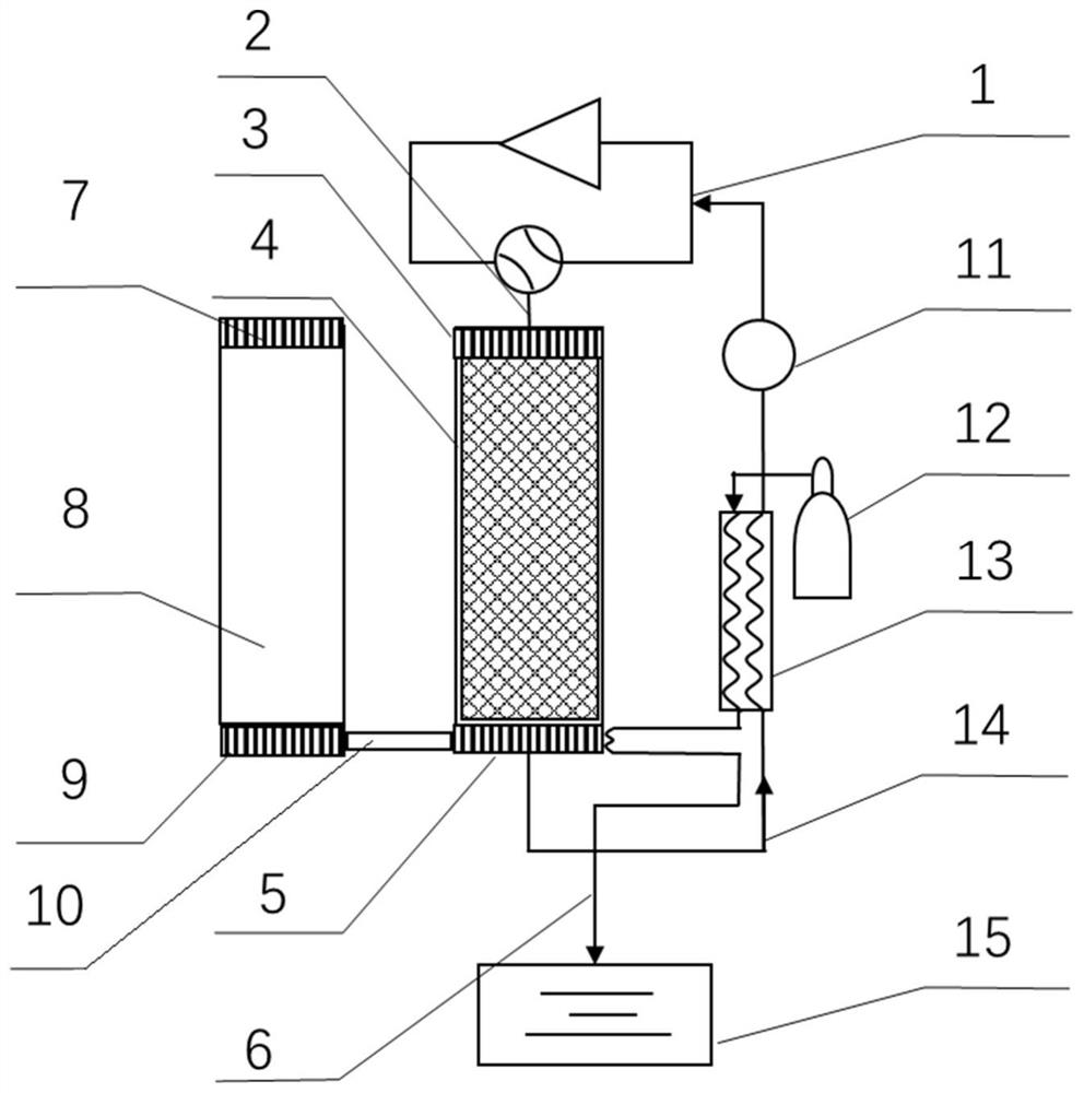
[0047] like figure 1 As shown, the high-efficiency liquefaction system using a direct current regenerative refrigerator in this embodiment includes a regenerative refrigeration module and a liquefaction module.

[0048] The regenerative cooling module consists of a regenerative chiller unit and a DC external circulation unit. The regenerative refrigerator unit includes compression device 1, compressor transfer pipe 2, regenerator hot end heat exchanger 3, regenerator 4, regenerator cold end heat exchanger 5, direct current circulation pipeline 6, expansion mechanism (eductor or vessel) hot end heat exchanger 7, expansion mechanism (eductor or vessel) 8, expansion mechanism (eductor or vessel) cold end heat exchanger 9, regenerator and expansion mechanism (eductor or vessel) transfer tube 10. The DC external circulation unit includes a DC outlet pipe 6 and a DC external circulation control assembly 11 .

[0049] The liquefaction module includes a high-pressure gas source 12 ...

Embodiment 2

[0059] like Figure 4 Shown, the GM type pulse tube refrigerator of embodiment 2 and two-way intake valve group, structure and figure 1 The structure of the refrigerator shown is basically the same, the difference is that the regenerative refrigerator is a GM pulse tube refrigerator, and the compression device 1 of the GM pulse tube refrigerator consists of a high pressure control valve 22, a low pressure control valve 23, a scroll compression Machine 24 is formed, and two-way intake valve group 25 is made up of two one-way valves antiparallel.

[0060] The connections between the components are:

[0061] The compression device 1 is connected by a scroll compressor 24, a high-pressure control valve 22 and a low-pressure control valve 23 through pipelines sequentially, the compressor transmission pipe 2, the heat exchanger 3 at the hot end of the regenerator, the regenerator 4, and the regenerator cold End heat exchanger 5, regenerator and expansion mechanism (vessel) transfe...

Embodiment 3

[0068] like Figure 5 Shown, the structural representation of the two-stage GM refrigerator of embodiment 3, structure and figure 1 The structure of the refrigerator shown is basically the same, the difference is that the regenerative refrigerator is a GM refrigerator, and the compression device 1 of the GM refrigerator consists of a piston compressor 27, a post-stage water cooler 28, a high-pressure balance tank 29, an air intake Valve 30, exhaust valve 31 and low-pressure balance tank 32; in addition, it is necessary to add a primary regenerator 33, a primary hot end device 34, a primary cylinder 35, a secondary cylinder 36 and a primary counterflow heat exchanger 37 .

[0069] The connections between the components are:

[0070]The compression device 1 is connected by pipelines sequentially by a piston compressor 27, a post-stage water cooler 28, a high-pressure balance tank 29, an intake valve 30, an exhaust valve 31, and a low-pressure balance tank 32. End heat exchang...


PUM


Abstract

The invention relates to an efficient liquefaction system of a regenerative refrigerator adopting direct currents. The efficient liquefaction system comprises a regenerative refrigerating module and aliquefaction module. The regenerative refrigerating module comprises a regenerative refrigerator unit and a direct-current external circulation unit. The regenerative refrigerator unit comprises a compression device, a heat regenerator hot end heat exchanger, a heat regenerator, a heat regenerator cold end heat exchanger, an expansion mechanism cold end heat exchanger, an expansion mechanism andan expansion mechanism hot end heat exchanger which are connected in sequence. Compared with the prior art, the heat exchange heat resistance is smaller, the efficient liquefaction system is particularly suitable for a compact GM refrigerator with excellent refrigerating performance, due to the fact that the heat regenerator is arranged in an air cylinder and an air gap inevitably exists between the heat regenerator and the air cylinder, only a liquefied working medium flow channel can be wound around the outer side of the air cylinder, and large air gap heat resistance exists with heat exchange of the heat regenerator; and the direct currents led out from the interior are in close contact with regenerative filler and alternating currents, so that almost no heat exchange temperature difference exists, and the heat resistance can be effectively reduced.

Description

technical field [0001] The invention relates to the technical field of refrigeration, in particular to a high-efficiency liquefaction system using a direct current regenerative refrigerator. Background technique [0002] Regenerative cryogenic refrigerators have the advantages of high reliability, simple structure, and high flexibility, and are widely used in low-temperature technologies such as gas liquefaction and superconductivity. [0003] An ideal recuperative cryogenic refrigerator such as a pulse tube refrigerator does not have direct flow in operation. However, with the introduction of the two-way air intake structure, a closed loop consisting of the two-way air intake valve, the regenerator and the vessel is formed. This loop induces DC flow, which is also called Gedeon DC because it was first formally proposed and theoretically demonstrated by Gedeon. It was initially believed that the DC phenomenon would have a serious impact on the stability and cooling efficie...

Claims


Application Information

Patent Timeline
IPC IPC(8): F25B40/06F25B41/00
CPCF25B40/06F25B2600/25F25B2309/1408
Inventor 曹强栾铭凯霍斌
Owner TONGJI UNIV
Why Eureka
Try Eureka