Conduit welding shrinkage control device

A technology for controlling device and shrinkage, applied in welding equipment, auxiliary devices, auxiliary welding equipment, etc., can solve the problems of difficult control of catheter accuracy, reduction of welding speed, disorder of lateral shrinkage, etc., to ensure welding accuracy and product quality, Easy and fast to use, operate the effect of editing

Active Publication Date: 2021-09-07
CHENGDU AIRCRAFT INDUSTRY GROUP
View PDF7 Cites 0 Cited by
  • Summary
  • Abstract
  • Description
  • Claims
  • Application Information

AI Technical Summary

Problems solved by technology

At the same time, due to its complex three-dimensional space size and small batch production quantity, the entire manufacturing process of the catheter needs to use the numerical control pipe bending process and welding process. Both of these two processes have long-term difficulties in controlling the amount of springback and welding shrinkage of the pipe. Due to the technical bottleneck, when the catheter is assembled and positioned on the welding fixture, the amount of welding shrinkage cannot be predicted, and the precision of the finished catheter is difficult to control, which restricts the improvement of the accuracy of the catheter
Moreover, the current flexible intelligent technology is difficult to link the full data of the manufacturing process, and there are inevitably certain data variable errors between the digital model and the product, which also directly affects the digital production and data control of welded catheter manufacturing, and cannot be realized based on Digital manufacturing of current conditions
[0003] At the same time, since the weld shape of the conduit is a circular weld, which does not involve complicated welding methods such as multi-layer welding of thick plates, the welding shrinkage of the conduit is mainly affected by the lateral shrinkage of the welding, and the angular error is also mainly affected by the various welding methods of the conduit. Influence of inconsistency of lateral shrinkage value of weld section
For thin plates, the welding gap has a great influence on the input of welding heat. The larger the gap of the welding seam, the greater the lateral shrinkage of the welding. Theoretically, the shrinkage value of the welding seam with zero distance is The same, but not equidistant welds, the transverse shrinkage will be disordered, and it is difficult to implement engineering control by quantifying variables
During welding, the operator is forced to reduce the welding speed and melt more electrodes to fill the welding gap at the larger weld seam, which causes fluctuations in the welding speed and changes in the welding heat input, resulting in disordered shrinkage coefficient and Angular error increases
The irregular gap of the conduit is harmful to the welding control, making the relationship of various variables indistinguishable and difficult to control. The premise of controlling the lateral shrinkage of the welding is to control the welding gap

Method used


Image

  • Conduit welding shrinkage control device
  • Conduit welding shrinkage control device
  • Conduit welding shrinkage control device

Examples


Embodiment 1

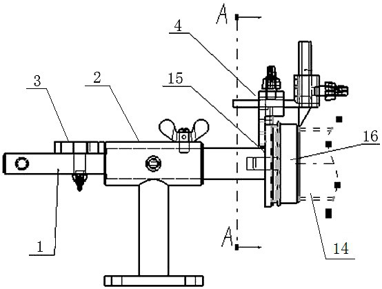
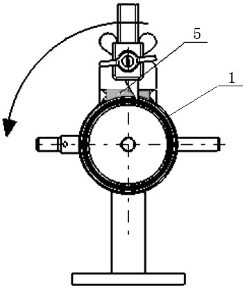
[0031] This example provides figure 1 A catheter welding shrinkage control device is shown, which is used to control the welding shrinkage in the welding process. Before welding, the shrinkage distance of the catheter 14 is reserved to prevent the overall connection accuracy of the catheter 14 caused by the displacement of multiple pipe joints 16. low problem. It includes a conduit 14 and a pipe joint 16 connected to the end of the conduit 14, and also includes a digital control device and a pipe marking device 4. The digital control device includes a casing positioner 1, a pipe support 2 and a digital measuring device 3. The casing positioning One end of the device 1 is provided with a connection plate 15, through which the casing positioner 1 is coaxially connected with the pipe joint 16, the pipe support 2 is used to support the casing positioner 1, and the middle section of the casing positioner 1 is inserted into the In the pipe support 2, a stop screw 12 and a latch 13 ...

Embodiment 2

[0036] This embodiment is based on the whole content of embodiment 1, the difference is:

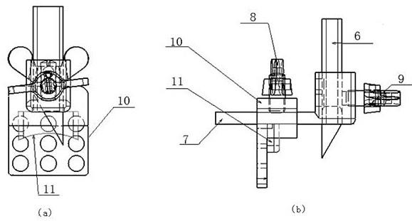
[0037] Further, the pipe marking device 4 is used in conjunction with a digital control device, the numerical control device obtains the welding shrinkage variable, and transmits it to the pipe marking device 4, and the pipe marking device 4 obtains the position of the weld seam before welding , so as to determine the processing benchmark. The function of the pipe marking device 4 is to map the weld line on the conduit. Since the weld line includes the welding shrinkage value, in order to ensure that the pipe marking device can automatically adapt to the welding shrinkage value, the main installation surface of the piping marking device is selected Only on the sleeve can it be ensured that it can adapt to the follow-up when adjusting the welding shrinkage value, and ensure the effectiveness of the reading accuracy of the digital controller; Different diameters and different casings, dif...


PUM


Abstract

The invention discloses a catheter welding shrinkage control device, which belongs to the technical field of precision manufacturing of aviation welding catheters. It includes a digital control device and a pipe marking device. The digital control device includes a casing positioner, a pipe support and a digital measuring device. A connection plate is provided at one end of the casing positioner. The joints are coaxially connected, and the pipe support is used to support the casing positioner; the digital measuring device is rotatably connected to the casing positioner, and rotating the digital measuring device can drive the casing positioner to slide in the pipe support; The scriber is fixed on the connection plate, and is used to draw a circle of welding seam line at the junction of the conduit and the pipe joint. In the present invention, the digital control device and the pipe marking device are used in conjunction with each other, the welding shrinkage variable is obtained by the digital control device, and transmitted to the pipe marking device, and the position of the weld seam before welding is obtained by the pipe marking device, so that there is no gap Welding requires technical support.

Description

technical field [0001] The invention relates to a welding fixture, in particular to a control device for welding shrinkage of a conduit. Background technique [0002] For precision welded conduits used in aviation, with the iterative upgrade of aircraft, the manufacturing accuracy of conduits is becoming more and more strict. According to the requirements of manufacturing standards, the end face accuracy is required to be controlled at ±0.16mm, and the accuracy requirements are relatively high. At the same time, due to its complex three-dimensional space size and small batch production quantity, the entire manufacturing process of the catheter needs to use the numerical control pipe bending process and welding process. Both of these two processes have long-term difficulties in controlling the amount of springback and welding shrinkage of the pipe. Due to the technical bottleneck, when the catheter is assembled and positioned on the welding fixture, because the amount of weld...

Claims


Application Information

Patent Timeline
Patent Type & Authority Patents(China)
IPC IPC(8): B23K37/053B25H7/04
CPCB23K37/053B25H7/04
Inventor 黄兴成金晓波贾俊杰
Owner CHENGDU AIRCRAFT INDUSTRY GROUP
Why Eureka
Try Eureka