Evaporator and process for continuously producing 38-58% liquid calcium chloride
A calcium chloride liquid and evaporator technology, applied in evaporation, chemical instruments and methods, separation methods, etc., can solve the problems of inability to continuously produce, reduce heat exchange efficiency, affect evaporation rate, etc., and achieve high evaporation intensity and comprehensive energy. The effect of reducing consumption and shortening the process flow
- Summary
- Abstract
- Description
- Claims
- Application Information
AI Technical Summary
Problems solved by technology
Method used
Image
Examples
Embodiment 1
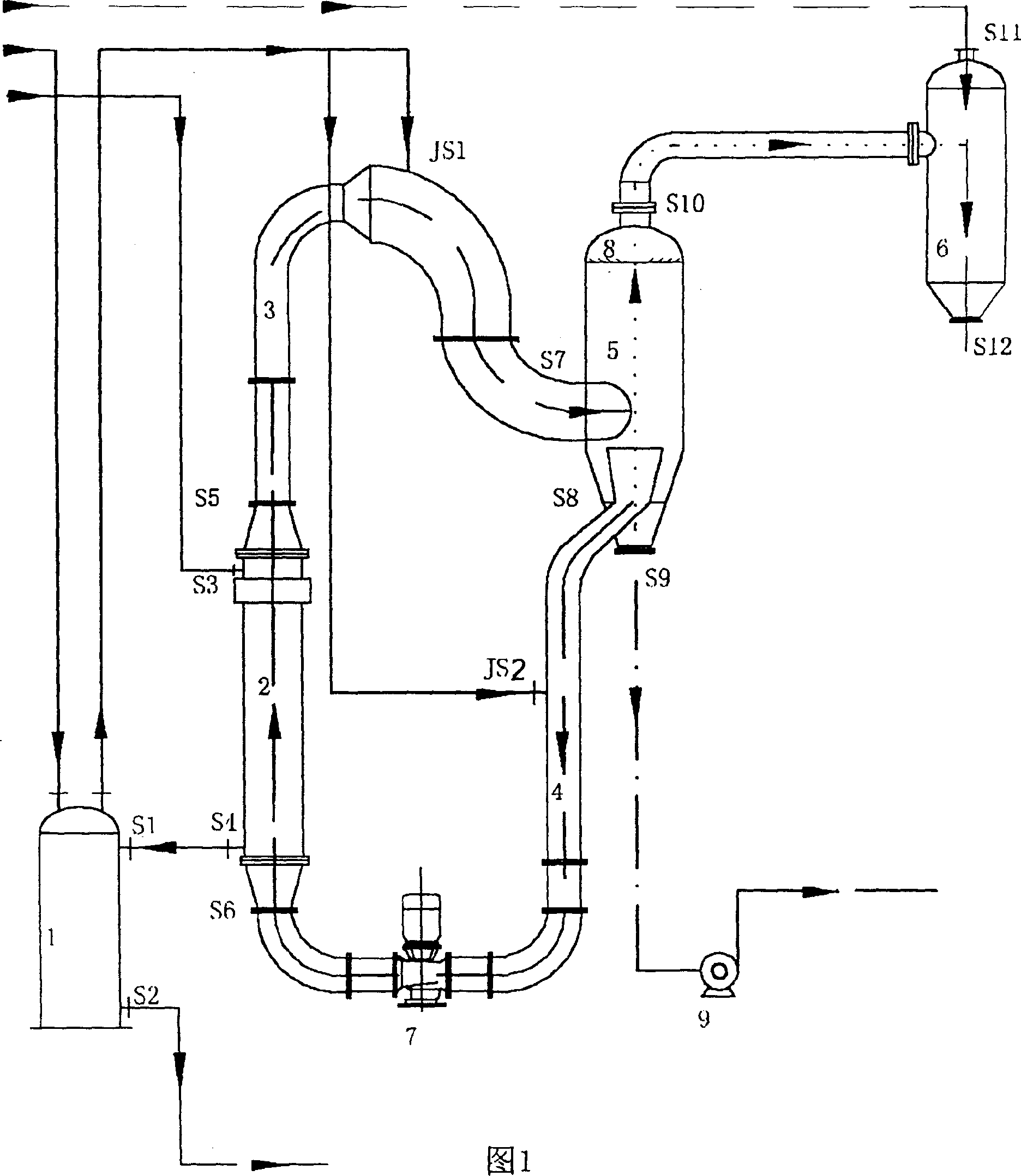
[0035] The structure of the corrugated tube evaporator is shown in Figure 1. The preheater 1 is connected to the heating chamber 2 through pipelines. The heating chamber is connected to the separation chamber 5 through the upper and lower circulation pipes 3 and 4 respectively. The separation chamber is connected to the condensing chamber through pipelines. 6, the circulation pump 7 is installed on the lower circulation pipe, and the liquid outlet pump 9 is installed on the liquid outlet pipe. The heating chamber of the evaporator is made of titanium or stainless steel, and the upper circulation pipe 3 is made of a variable diameter pipe that becomes thinner and thicker. Inverted U-shaped pipe, the circulation liquid outlet S8 of the lower circulation pipe is drawn from the center of the separation chamber, and the liquid inlet of the raw material liquid is set at the downside JS1 of the inverted U-shaped pipe of the upper circulation pipe and the upper part of the downlink sect...
Embodiment 2
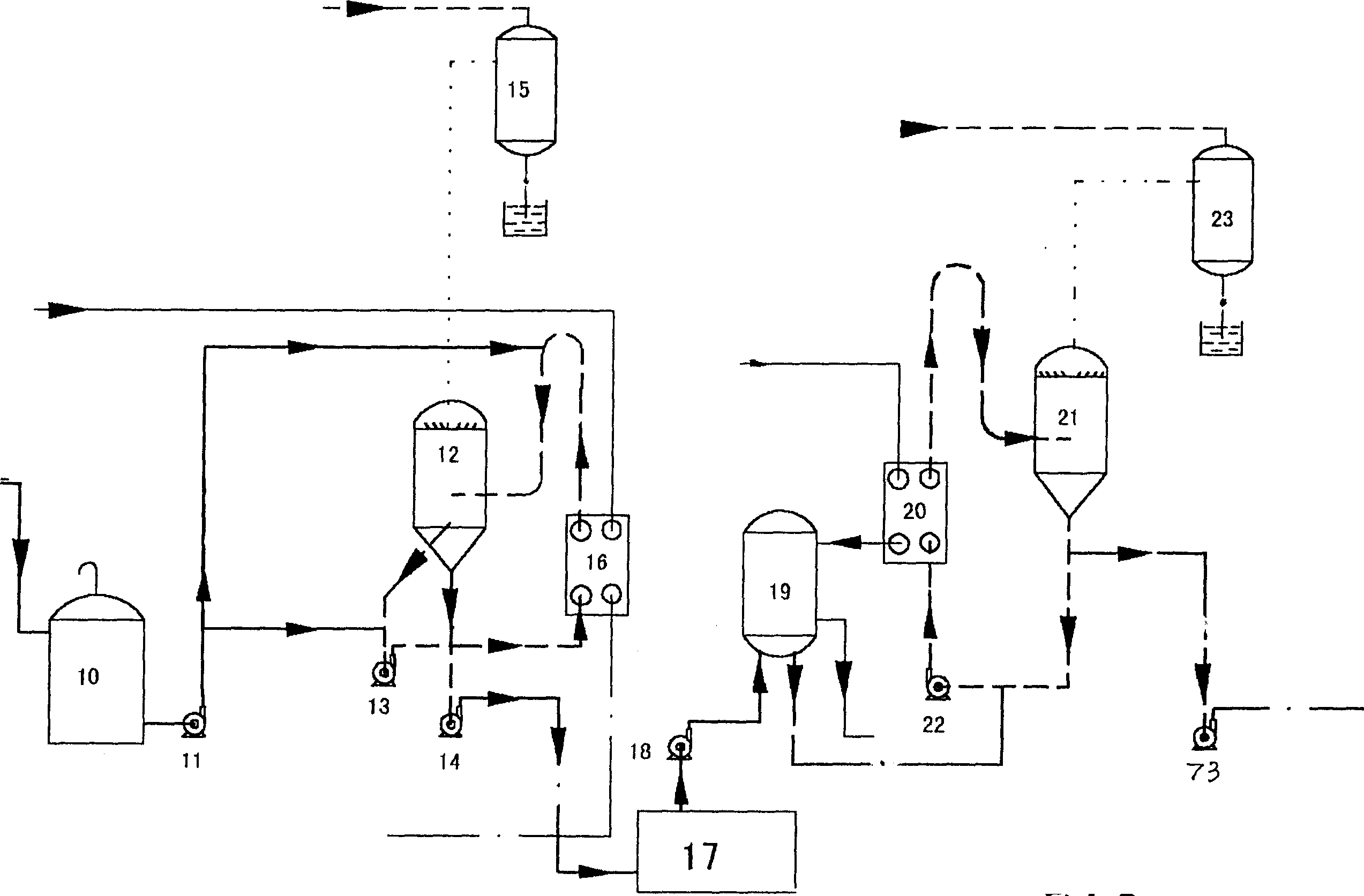
[0045] Double-single-effect evaporation process is adopted. The structure of the evaporator is the same as in Example 1.
[0046] The technological process for continuous production of 38% to 58% calcium chloride liquid by double-single-effect adiabatic evaporation is as follows: figure 2 As shown: that is, the low-enthalpy steam enters the heating chamber from the steam side of the heating chamber 16 of the evaporator, and the raw material liquid flowing out from the raw material liquid storage tank 10 is pumped into the side entrance of the inverted U-shaped pipe of the upper circulation pipe 3 by the raw material liquid pump 11 After entering the separation chamber 12, the circulating liquid drawn from the center of the separation chamber is pumped into the heating chamber 16 through the circulating pump 13, and the finished liquid flowing out from the bottom of the separation chamber is pumped into the desalination system 17 through the outlet pump 14. After the single-ef...
Embodiment 3
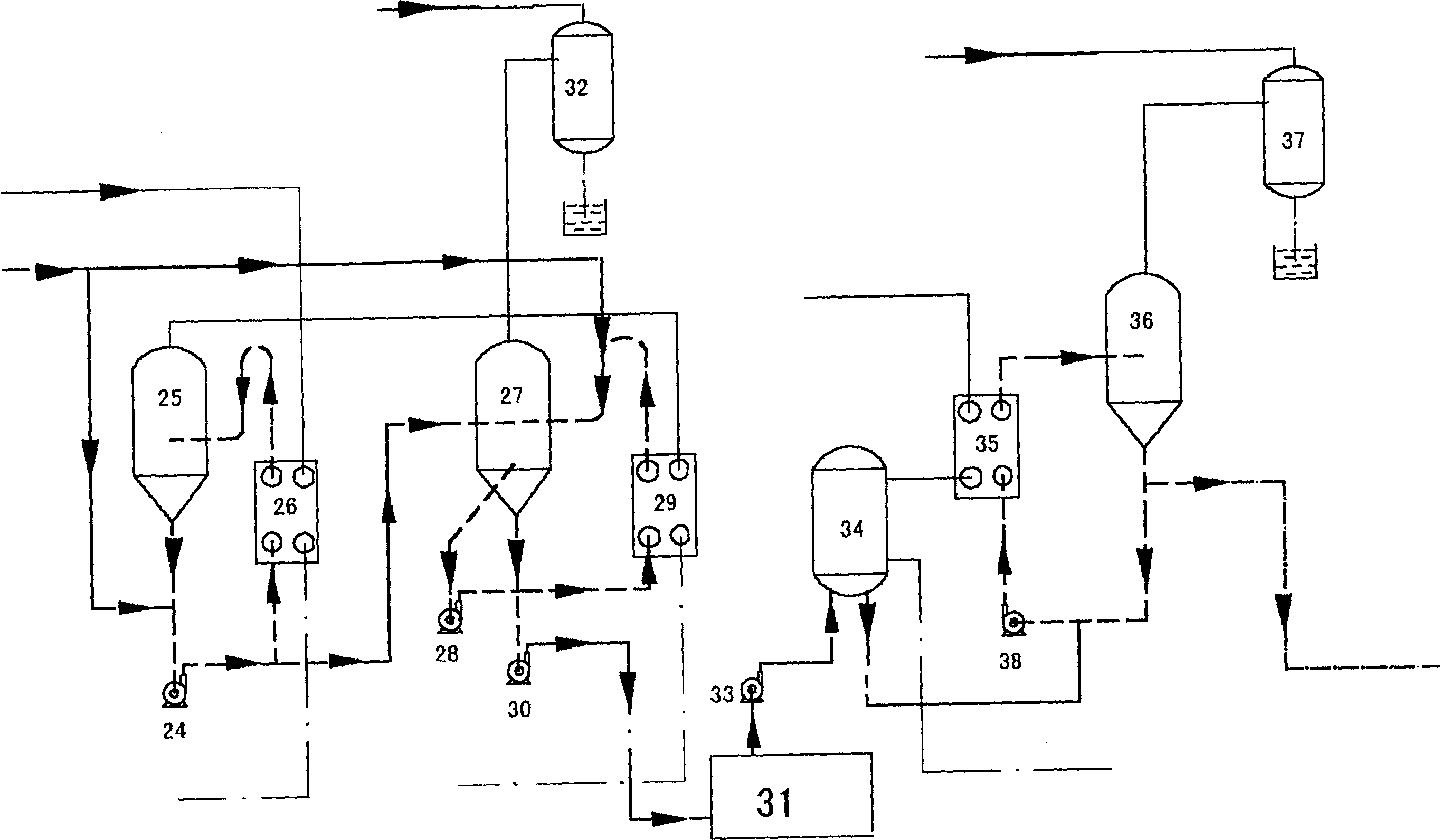
[0048] A multi-effect evaporation process combining downflow and flow is adopted. The structure of the evaporator is the same as in Example 1.
[0049] The process flow of continuous production of 38% to 58% calcium chloride liquid by multi-effect evaporation combined with flow and flow is as follows: image 3 Shown: Add the by-product salt of the desalination process into the I-effect evaporation system as the scale dissolution medium when driving. After preheating, the raw material solution with a concentration of 10% and a temperature of 80°C enters from the upper part of the I-effect pump 24 and the downlink side of the II-effect upper circulation pipe at the same time, and the finished liquid after flashing through the I-effect separation chamber 25 is mixed with the raw material solution After that, the I-effect pump 24 is pumped into the I-effect heating chamber 26 and the II-effect separation chamber 27 respectively, and the circulating liquid flowing out from the II-...
PUM
 Abstract
Description
Claims
Application Information
 - R&D
- Intellectual Property
- Life Sciences
- Materials
- Tech Scout
- Unparalleled Data Quality
- Higher Quality Content
- 60% Fewer Hallucinations
Browse by: Latest US Patents, China's latest patents, Technical Efficacy Thesaurus, Application Domain, Technology Topic, Popular Technical Reports.
© 2025 PatSnap. All rights reserved.Legal|Privacy policy|Modern Slavery Act Transparency Statement|Sitemap|About US| Contact US: help@patsnap.com


