Method for improving surface roughness of shielding gate

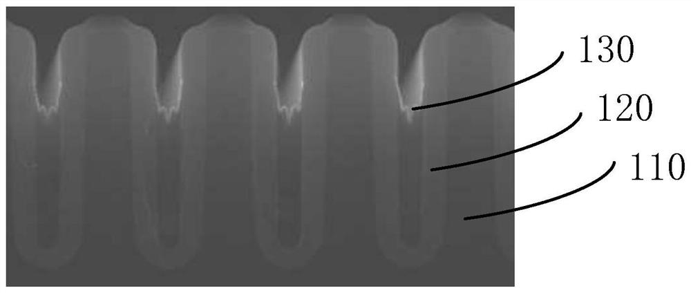
A technology of rough surface and shielding grid, applied in the field of improving the surface roughness of shielding grid, can solve the problems affecting the leakage performance of control grid and shielding grid, pits and unevenness of unevenness

Pending Publication Date: 2020-12-25
SHANGHAI HUAHONG GRACE SEMICON MFG CORP
View PDF5 Cites 0 Cited by
  • Summary
  • Abstract
  • Description
  • Claims
  • Application Information

AI Technical Summary

Problems solved by technology
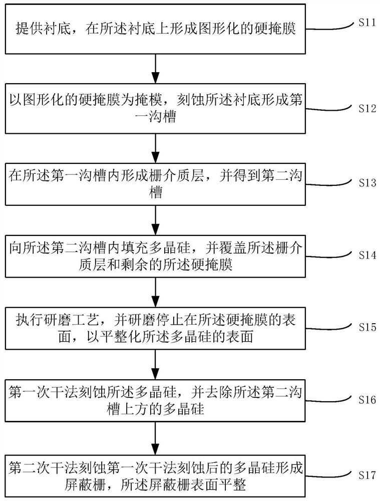
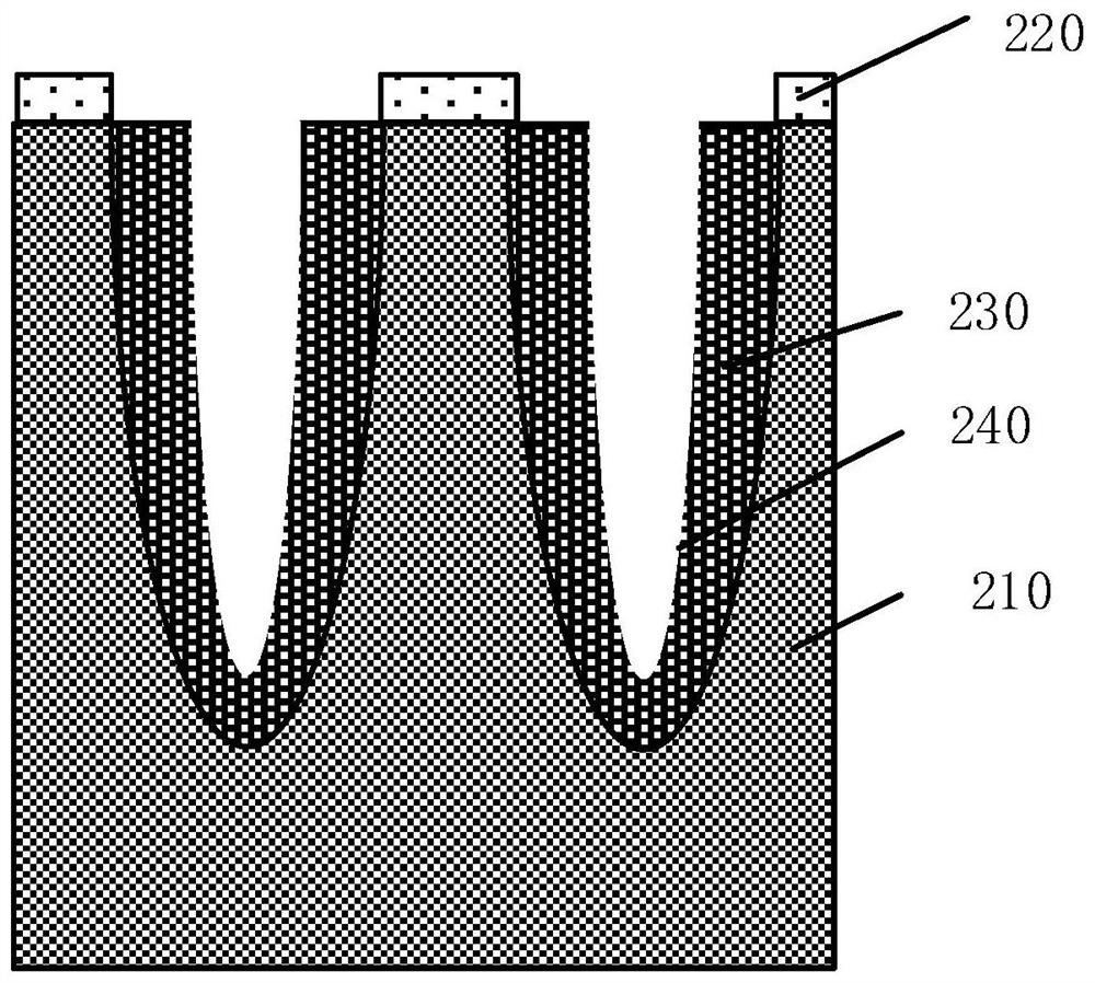
However, with the development of the process, the size of the opening of the second trench is gradually reduced. When etching polysilicon to form the shield gate 130, the surface of the shield gate 130 will appear uneven, even in the depth of the first trench. When the width ratio is greater than or equal to...

Method used


Image

  • Method for improving surface roughness of shielding gate
  • Method for improving surface roughness of shielding gate
  • Method for improving surface roughness of shielding gate

Examples


Embodiment Construction

[0032] The specific implementation manner of the present invention will be described in more detail below with reference to schematic diagrams. The advantages and features of the present invention will be more apparent from the following description. It should be noted that all the drawings are in a very simplified form and use imprecise scales, and are only used to facilitate and clearly assist the purpose of illustrating the embodiments of the present invention.

[0033] Hereinafter, the terms "first", "second", etc. are used to distinguish between similar elements, and are not necessarily used to describe a specific order or chronological order. It is to be understood that these terms so used are interchangeable under appropriate circumstances. Similarly, if a method described herein includes a series of steps, the order in which these steps are presented is not necessarily the only order in which these steps can be performed, and some described steps may be omitted and / or...


PUM


Abstract

The invention provides a method for improving the surface roughness of a shielding gate. The method comprises the steps of providing a substrate, and forming a graphical hard mask on the substrate; taking the graphical hard mask as a mask, and etching the substrate to form a first trench; forming a gate dielectric layer in the first trench, and obtaining a second trench; filling the second trenchwith polycrystalline silicon, and covering the gate dielectric layer and the residual hard mask; executing a grinding process, and stopping grinding on the surface of the hard mask to flatten the surface of the polycrystalline silicon; performing dry etching on the polycrystalline silicon for the first time, and removing the polycrystalline silicon above the second trench; and carrying out seconddry etching on the polycrystalline silicon subjected to the first dry etching to form a shielding gate, wherein the surface of the shielding gate is flat. The problem that the surface of the formed shielding gate is rough can be solved, so that a process window of a dielectric layer formed between the shielding gate and the control gate is increased, and the electric leakage performance between the control gate and the shielding gate is improved.

Description

technical field [0001] The invention relates to the technical field of semiconductors, in particular to a method for improving surface roughness of a shielding grid. Background technique [0002] In the field of medium and low voltage devices with a withstand voltage of 100v and below, Shield Gate Trench (SGT) devices are widely used because of their low specific on-resistance and low gate-drain coupling capacitance. The gate structure of shielded gate trench devices includes shielded polysilicon and polysilicon gate. Shielded polysilicon is usually also called source polysilicon, which are all formed in the trench. According to the different settings of shielded polysilicon and polysilicon gate in the trench, it is usually divided into upper and lower gates. structure and left-right structure. In the upper and lower structure, the shielding polysilicon is located at the bottom of the trench, the polysilicon gate is located at the top of the trench, and the polysilicon gate...

Claims


Application Information

Patent Timeline
IPC IPC(8): H01L21/28H01L21/321H01L21/3213
CPCH01L21/28035H01L21/28114H01L21/32115H01L21/32135
Inventor 李秀然邬镝薛华瑞
Owner SHANGHAI HUAHONG GRACE SEMICON MFG CORP
Why Eureka
Try Eureka