
Hydrogenation process and system for producing catalytically reformed raw material

A technology of catalytic reforming and raw materials, which is applied in the field of hydrocarbon oil cracking, can solve the problems of low yield of catalytic reforming raw materials and low latent content of aromatics, and achieve the effects of improving economic benefits of enterprises, reducing production costs and increasing selectivity

Active Publication Date: 2020-12-29
CHINA PETROLEUM & CHEM CORP +1
View PDF6 Cites 3 Cited by
  • Summary
  • Abstract
  • Description
  • Claims
  • Application Information

AI Technical Summary

Problems solved by technology

[0008] The purpose of the present invention is to provide a hydrogenation method and system for producing catalytic reforming raw materials on the basis of the prior art. Low rate and low potential content of aromatics

Method used


Image

  • Hydrogenation process and system for producing catalytically reformed raw material
  • Hydrogenation process and system for producing catalytically reformed raw material
  • Hydrogenation process and system for producing catalytically reformed raw material

Examples


Embodiment 1

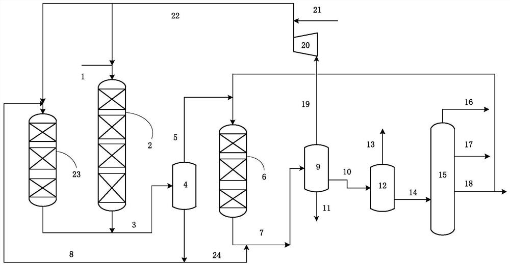
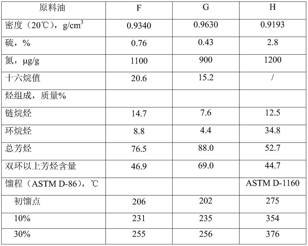
[0050] The mixed raw material of raw oil F and H enters the first hydrogenation reaction zone together with hydrogen, and reacts with the hydrofining catalyst A, and the reaction effluent enters the first high-pressure separator for gas-liquid separation, and the obtained first liquid phase stream enters The reaction is carried out in the second hydrogenation reaction zone equipped with the hydrocracking catalyst C, and the reaction product in the second hydrogenation reaction zone is recycled to the first high-pressure separator. The obtained first gas-phase stream enters the third hydrogenation reaction zone equipped with hydrocracking catalyst E for reaction, and the reaction effluent enters the second high-pressure separator, and the obtained second liquid-phase stream enters the fractionation tower to obtain light naphtha fraction , heavy naphtha fraction and diesel fraction, and the diesel fraction is returned to the third hydrogenation reaction zone for circulation conve...

Embodiment 2

[0054] The mixed raw material of raw oil G and H enters the first hydrogenation reaction zone together with hydrogen, and reacts with the hydrogenation catalyst B. The reaction effluent enters the first high-pressure separator for gas-liquid separation, and the obtained first liquid phase stream enters the The reaction is carried out in the second hydrogenation reaction zone equipped with the hydrocracking catalyst D, and the reaction product in the second hydrogenation reaction zone is recycled to the first high-pressure separator. The obtained first gas-phase stream enters the third hydrogenation reaction zone equipped with hydrocracking catalyst E for reaction, and the reaction effluent enters the second high-pressure separator, and the obtained second liquid-phase stream enters the fractionation tower to obtain light naphtha fraction , heavy naphtha fraction and diesel fraction, and the diesel fraction is returned to the third hydrogenation reaction zone for circulation con...


PUM


Abstract

A hydrogenation method and system for producing a catalytically reformed raw material are characterized in that a mixed raw material rich in aromatic hydrocarbon diesel fraction and wax oil fraction is subjected to a hydrofining reaction in a first hydrogenation reaction zone, a reaction product enters a first high-pressure separator, a first liquid-phase material flow obtained through separationenters a second hydrogenation reaction zone, and an obtained product returns to the first high-pressure separator; and the separated first gas phase material flow enters a third hydrogenation reactionzone, the obtained reaction product is separated to obtain a light naphtha fraction, a heavy naphtha fraction and a diesel oil fraction, and the diesel oil fraction is circulated back to the third hydrogenation reaction zone. By adopting the method and the system provided by the invention, wax oil fractions mixed with a large proportion of aromatic hydrocarbon-rich diesel fractions can be processed, the heavy naphtha fractions with high aromatic hydrocarbon latent content can be obtained with high yield and high selectivity, and the heavy naphtha fractions are high-quality raw materials for catalytic reforming.

Description

technical field [0001] The invention relates to a hydrocarbon oil cracking method for obtaining low-boiling fractions in the presence of hydrogen, more specifically, a hydrogenation method and system for producing catalytic reforming raw materials from mixed raw materials. Background technique [0002] With the aggravation of heavy and inferior crude oil, the quality of FCC diesel is deteriorating and the output is increasing year by year. This part of FCC diesel accounts for about one third of my country's commercial diesel. At present, in order to extract more light oil products from crude oil, refineries continue to improve the processing capacity and processing depth of catalytic cracking units, resulting in further deterioration of the quality of catalytic cracking diesel oil, mainly manifested in high content of aromatics, sulfur and nitrogen, etc. High impurity content, low cetane number. At the same time, with the increasingly stringent environmental protection legi...

Claims


Application Information

Patent Timeline
IPC IPC(8): C10G67/14
CPCC10G67/14C10G2400/04C10G2300/1037C10G2300/1059C10G2300/1055
Inventor 赵广乐赵阳莫昌艺毛以朝董松涛
Owner CHINA PETROLEUM & CHEM CORP
Learn More