Eureka AIR delivers breakthrough ideas for toughest innovation challenges, trusted by R&D personnel around the world.

Combined electroplating equipment with flocculation function and electroplating method thereof

An electroplating equipment and combined technology, applied in chemical instruments and methods, flocculation/sedimentation water/sewage treatment, electrolysis process, etc., can solve the problems of wasting available resources, cumbersome electroplating steps, and low degree of mechanization, and achieve convenient flocculation treatment, facilitate electroplating work, and improve the effect of mechanization

Pending Publication Date: 2021-01-01
HEFEI UNIV OF TECH
View PDF7 Cites 1 Cited by
  • Summary
  • Abstract
  • Description
  • Claims
  • Application Information

AI Technical Summary

Problems solved by technology

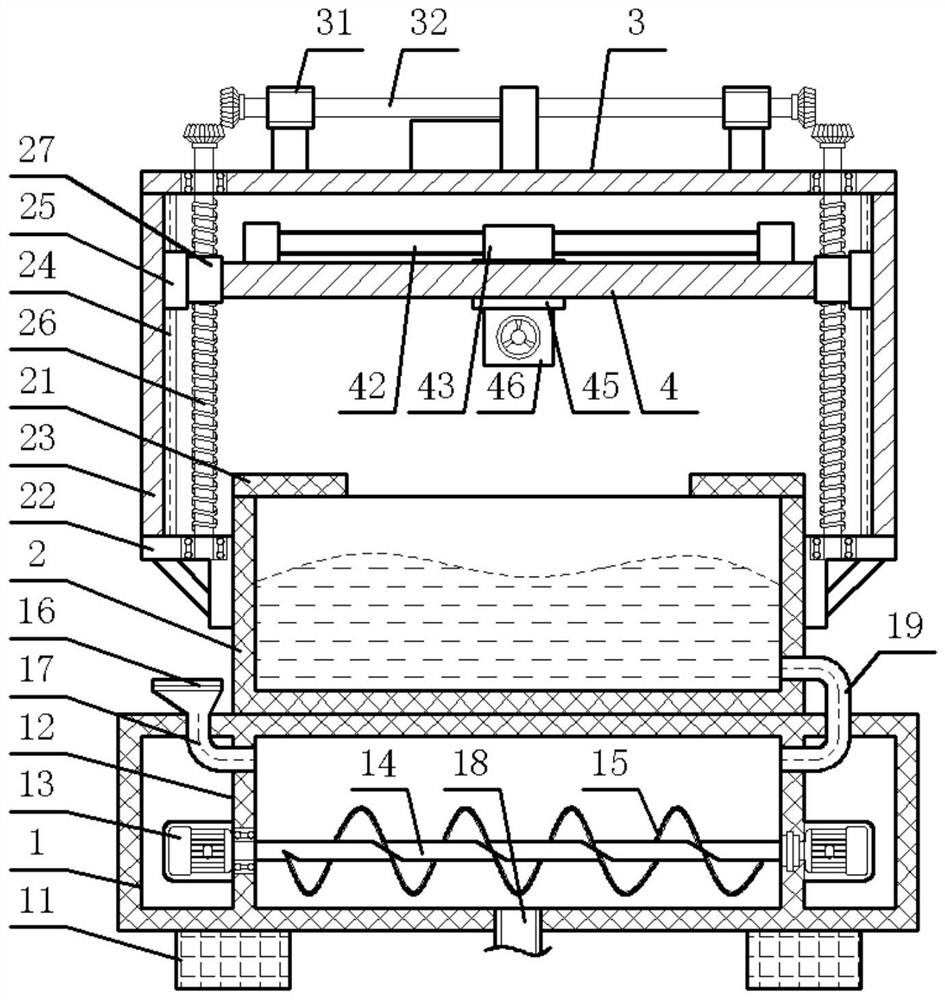
[0003] As a major problem in the electroplating production process, electroplating sewage treatment has the following problems: (1) Since there are many heavy metal ions in the electroplating sewage, it must be treated for environmental protection before it can be discharged , the traditional electroplating sewage treatment mostly directly removes heavy metal ions by precipitation, which is costly and wastes a lot of available resources; (2), when the existing electroplating equipment is performing electroplating work, the electroplating steps are relatively cumbersome and the degree of mechanization Low, it is not convenient to carry out flocculation and precipitation treatment on the electroplating solution after electroplating

Method used


Image

  • Combined electroplating equipment with flocculation function and electroplating method thereof
  • Combined electroplating equipment with flocculation function and electroplating method thereof
  • Combined electroplating equipment with flocculation function and electroplating method thereof

Examples


Embodiment 1

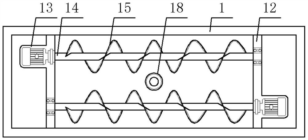
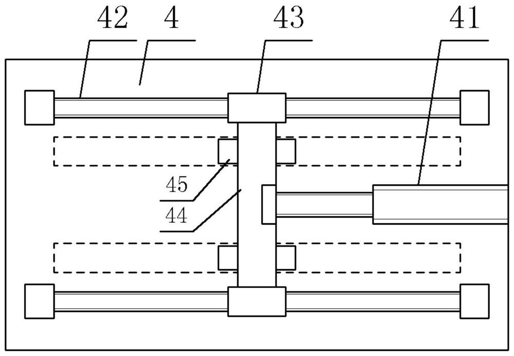
[0039] Example 1: In order to simplify the tedious operation steps of electroplating, improve the mechanization of electroplating operation, and further improve the efficiency of sewage treatment, a combined electroplating equipment with flocculation function is proposed in this example, see Figure 1-5 , including a flocculation box 1, an electroplating box 2, a stirring component, a lifting component, a driving mechanism, a sliding mechanism, and a clamping component. The flocculation box 1 is a rectangular box placed horizontally and horizontally, and the electroplating box 2 is open on the top surface. The bottom surface of the electroplating box 2 and the top surface of the flocculation box 1 are fixedly welded; the two sides of the flocculation box 1 are provided with a pair of sealing partitions 12, which are located between the pair of sealing partitions 12 and the flocculation box 1 A flocculation chamber is formed inside, and stirring components are staggeredly instal...

Embodiment 2

[0045] Embodiment 2: In order to realize manual clamping of the workpiece, in the present invention, the clamping assembly includes a manual wheel 53, a clamping threaded rod 52, and a clamping backing plate 5. The middle of the clamping plate 46 located in the front is provided with a A clamping threaded barrel 51 that penetrates through is provided with a clamping threaded rod 52 that spirally penetrates through the clamping threaded barrel 51, and a manual wheel 53 is provided at the outer end of the clamping threaded rod 52; located between the two clamping plates 46 A pair of clamping pads 5 are arranged between them, and the clamping plate 46 located at the rear is fixedly connected with the clamping pad 5 at the rear. The inner end of 52 is snap-fitted and inserted into the turning groove; the upper and lower ends of the threaded barrel 51 are recessed on the front clamping plate 46 with a pair of limit holes, and limit rods 54 for sliding connection are inserted into th...

Embodiment 3

[0046] Embodiment 3: In order to further realize the actual use operation to this application, refer to Image 6 , in this embodiment, the electroplating method of the combined electroplating equipment with flocculation function is proposed, comprising the following steps:

[0047] Step 1, the stirring motor 13 is electrically connected to the external power supply through the first power cord, the drive motor 33 is electrically connected to the external power supply through the second power cord, and the telescopic cylinder 41 is electrically connected to the external power supply through the third power cord; 2, pour an appropriate amount of electroplating solution, and place the workpiece to be electroplated on the middle of the top surface of the support plate 21;

[0048] In step 2, the lifting assembly is driven by the driving mechanism, and then the lifting plate 4 is driven down to an appropriate clamping height; the motor shaft of the driving motor 33 is controlled to...


PUM


Abstract

The invention discloses combined electroplating equipment with a flocculation function. The combined electroplating equipment comprises a flocculation box, an electroplating box, stirring assemblies,lifting assemblies, driving mechanisms, a sliding mechanism and a clamping assembly, wherein the stirring assemblies are arranged on each sealing partition plate in a staggered manner; the lifting assemblies are installed at the middle corners of the two side faces of the electroplating box; the driving mechanisms are installed on the top face of each transverse plate; a transversely-placed lifting plate is arranged over the top face of the flocculation box; the sliding mechanism is installed on the top face of the lifting plate; clamping plates are arranged on the bottom faces of two slidingplates in the sliding mechanism; and the clamping assembly is arranged between the two clamping plates. The invention further discloses an electroplating method of the combined electroplating equipment with the flocculation function. According to the combined electroplating equipment with the flocculation function provided by the invention, tedious operation steps of electroplating are simplified,the mechanization degree of the electroplating operation is improved, flocculation treatment of sewage after electroplating is facilitated through combined installation, and the sewage treatment efficiency is improved.

Description

technical field [0001] The invention relates to the technical field of electroplating sewage treatment, in particular to a combined electroplating equipment with flocculation function and an electroplating method thereof. Background technique [0002] Electroplating is the process of plating a thin layer of other metals or alloys on the surface of certain metals using the principle of electrolysis. (such as rust), improve wear resistance, electrical conductivity, reflectivity, corrosion resistance (copper sulfate, etc.) and enhance aesthetics. [0003] Electroplating sewage treatment is a major problem in the electroplating production process. There are the following problems for the sewage treatment after electroplating: (1) Since there are many heavy metal ions remaining in the electroplating sewage, it must be environmentally treated before it can be discharged. , the traditional electroplating sewage treatment is mostly to directly remove heavy metal ions, the cost is h...

Claims


Application Information

Patent Timeline
IPC IPC(8): C25D17/00C25D21/10C25D17/06C25D21/00C02F1/52C02F101/20C02F103/16
CPCC25D17/00C25D21/10C25D17/06C25D21/00C02F1/5281C02F2101/20C02F2103/16
Inventor 王翔宇熊鸿斌匡武彭书传
Owner HEFEI UNIV OF TECH
Why Eureka
Eureka Blog
Learn More