Distributed optical fiber temperature sensing system and application thereof

A distributed optical fiber and sensing system technology, applied in the field of distributed sensing, can solve the problems of low temperature detection accuracy and short detection distance, so as to increase the temperature detection range, increase the output optical power, and improve the signal-to-noise ratio. Effect

Inactive Publication Date: 2021-01-12
姚峰
View PDF3 Cites 1 Cited by
  • Summary
  • Abstract
  • Description
  • Claims
  • Application Information

AI Technical Summary

Problems solved by technology

[0004] In view of the above deficiencies, the present invention discloses a distributed optical fiber temperature sensing system and its application, which solves the problems of short detection distance and low accuracy of temperature detection in the prior art distributed optical fiber temperature sensing system

Method used


Image

  • Distributed optical fiber temperature sensing system and application thereof
  • Distributed optical fiber temperature sensing system and application thereof

Examples


Embodiment 1

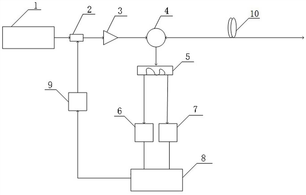
[0024] Such as figure 1 As shown, a distributed optical fiber temperature sensing system includes a 1550nm pulsed light source 1, a modulator 2, an optical fiber amplifier 3, a circulator 4, a bandpass filter 5, a first photodetector 6, a second photodetector device 7, signal processing device 8 and driver 9; the output end of the pulsed light source 1 is connected to the optical input end of the modulator 2 through an optical fiber, and the optical output end of the modulator 2 is connected to the input end of the optical fiber amplifier 3 through an optical fiber, so The output end of the optical fiber amplifier 3 is connected to the input end of the circulator 4 through an optical fiber, the first output end of the circulator 4 is connected to the optical fiber 10, the second output end of the circulator 4 is connected to the bandpass filter 5 The input port is connected, the first output end of the bandpass filter 5 is connected to the first photodetector 6 through an opti...


PUM


Abstract

The invention discloses a distributed optical fiber temperature sensing system, which comprises a pulse light source, a modulator, a circulator, a band-pass filter, a first photoelectric detector, a second photoelectric detector, a signal processing device and a driver, and an optical fiber amplifier is connected between the modulator and the circulator, and the input end of the optical fiber amplifier is connected with the light output end of the modulator; and the first light input end of the modulator is connected with the output end of the pulse light source, and the output end of the optical fiber amplifier is connected with the input end of the circulator. The system can be applied to long-distance temperature detection, the detection precision of signal light is high, the temperature detection range is wide, and the problems that a distributed optical fiber temperature sensing system in the prior art is short in detection distance and low in temperature detection precision are solved.

Description

technical field [0001] The invention belongs to the technical field of distributed sensing, and in particular relates to a distributed optical fiber temperature sensing system and its application. Background technique [0002] At present, there are many distributed temperature sensing technologies and methods based on optical fibers at home and abroad, but they are mainly based on OTDR (Optical Time Domain Reflectometry) technology and multiplexing (such as time division multiplexing, wavelength division multiplexing, frequency division multiplexing, etc.) using, etc.) technology. The laser emits pulsed laser light and transmits it along the sensing fiber, and at the same time continuously generates Stokes and anti-Stokes signal light that travels backward. The light intensity of the Stokes signal is so weak that it cannot be separated from the background noise, so the temperature signal at this distance cannot be detected. [0003] At present, the distributed optical fibe...

Claims


Application Information

Patent Timeline
Patent Type & Authority Applications(China)
IPC IPC(8): G01K11/32G01D5/353
CPCG01K11/32G01D5/35354
Inventor 姚峰
Owner 姚峰
Why Eureka
Try Eureka