RFID label detector

A technology of RFID tags and detectors, which is applied to computer components, electromagnetic radiation induction, instruments, etc., can solve problems such as lowering the quality of inspection, deviation from the feeding route, and easy short circuits, etc., to improve the quality of inspection, ensure straight feeding, The effect of improving scanning accuracy

Inactive Publication Date: 2021-01-12
宋悦
View PDF1 Cites 1 Cited by
  • Summary
  • Abstract
  • Description
  • Claims
  • Application Information

AI Technical Summary

Problems solved by technology

[0004] In the process of realizing the present invention, the inventor found that at least the following problems in the prior art have not been resolved: 1. For the problem of low cost performance of automation equipment used by small and medium-sized enterprises, the prior art detects the appearance by rapid human eyes and manually reads and writes the test , to realize the detection of the electronic label, which has the characteristics of simple structure and low cost, but the prior art label tape is easily affected by the vibration of the motor and the external force during transmission, and then deviates from the feeding route, which reduces the detection accuracy and further reduces the Inspection quality; 2. The label tape needs to be spread and fed during inspection, but for small and medium-sized enterprises, it is difficult to provide a dust-free environment for inspection, and there are many printed circuits on the surface of the electronic label, which is easy to get dusty during the inspection process , resulting in easy short circuit during use, affecting the normal use of electronic tags

Method used


Image

  • RFID label detector
  • RFID label detector
  • RFID label detector

Examples


Embodiment Construction

[0036] The following will clearly and completely describe the technical solutions in the embodiments of the present invention with reference to the accompanying drawings in the embodiments of the present invention. Obviously, the described embodiments are only some, not all, embodiments of the present invention. Based on the embodiments of the present invention, all other embodiments obtained by persons of ordinary skill in the art without making creative efforts belong to the protection scope of the present invention.

[0037] In describing the present invention, it is to be understood that the terms "center", "longitudinal", "transverse", "length", "width", "thickness", "upper", "lower", "front", " Back", "Left", "Right", "Straight", "Horizontal", "Top", "Bottom", "Inner", "Outer", "Clockwise", "Counterclockwise", etc. or The positional relationship is based on the orientation or positional relationship shown in the drawings, which is only for the convenience of describing t...


PUM


Abstract

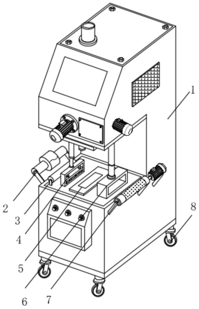
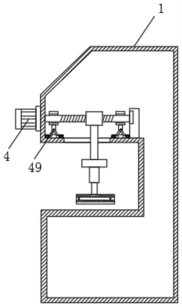
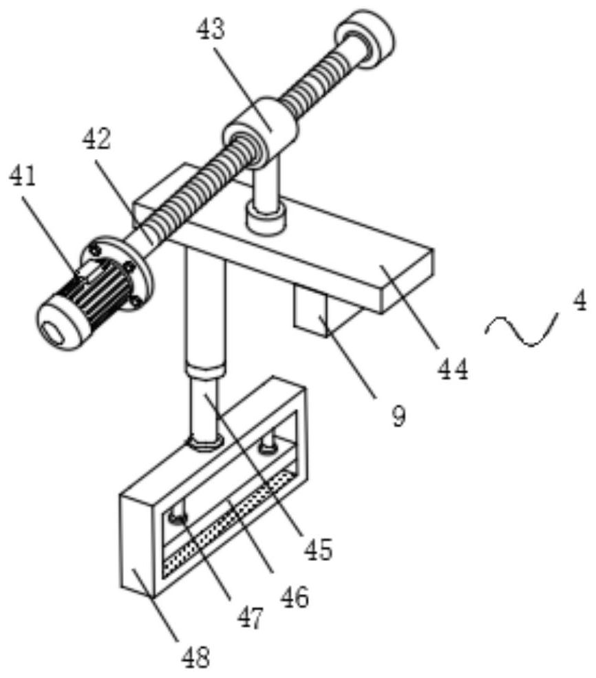
The invention discloses an RFID label detector which comprises a shell, a working assembly, a deviation rectifying mechanism, a dust washing mechanism and a control mechanism. The a working assembly,the deviation rectifying mechanism, the dust washing mechanism and the control mechanism are sequentially arranged on the shell. The working assembly comprises a discharging roller, a guide roller, ascanner, a receiving roller and rollers. the rollers are arranged at edges of the lower end of the shell; a working platform is arranged at the front end of the shell, and the guide roller and the scanner are sequentially arranged on the working platform; the discharging roller and the receiving roller are symmetrically arranged at the positions, close to the working platform, of the side surfaceof the shell. By arranging the deviation rectifying mechanism, the clamping plate arranged in the frame body can fix a label belt through the second telescopic rod, then position deviation rectifyingin the horizontal direction is conducted on the label under driving of a first sliding sleeve, deviation rectifying in the vertical position can be conducted on the label belt through the second telescopic rod, and linear feeding of the label belt can be guaranteed; the scanning precision and the detection quality are improved, and meanwhile, the deviation rectifying efficiency is relatively high.

Description

technical field [0001] The invention relates to the technical field of electronic label detection, in particular to an RFID label detection machine. Background technique [0002] Radio frequency identification technology (RFID) is a kind of automatic identification technology. Radio frequency identification technology uses radio waves without contact with fast information exchange and storage technology, uses wireless communication combined with data access technology, and then connects to the database system to achieve non-contact Two-way communication, so as to achieve the purpose of identification, for data exchange, a very complex system is connected in series. In the identification system, the reading, writing and communication of electronic tags are realized through electromagnetic waves. According to the communication distance, it can be divided into near-field and far-field. For this reason, the data exchange method between the read / write device and the electronic ta...

Claims


Application Information

Patent Timeline
IPC IPC(8): G06K7/10B25H1/00
CPCB25H1/00G06K7/10009
Inventor 宋悦尹强强
Owner 宋悦
Why Eureka
Try Eureka