Eureka AIR delivers breakthrough ideas for toughest innovation challenges, trusted by R&D personnel around the world.

High-voltage power amplifier for piezoelectric ceramic vibration platform

A technology of piezoelectric ceramics and vibration platform, which is applied to power amplifiers, improved amplifiers to improve efficiency, etc., can solve the problems of reduced AC impedance, large circuit power loss, and reduced voltage, and achieve the effect of reducing matching resistance and improving performance

Pending Publication Date: 2021-01-12
GENERAL ENG RES INST CHINA ACAD OF ENG PHYSICS
View PDF0 Cites 0 Cited by
  • Summary
  • Abstract
  • Description
  • Claims
  • Application Information

AI Technical Summary

Problems solved by technology

If it is applied to high-voltage, high-frequency, and high-power output occasions, there are defects such as large circuit power loss and low conversion efficiency, especially in the case of piezoelectric ceramic loads with large equivalent capacitance, it is difficult to output high voltage at high frequencies. question
In the prior art, the power amplifier driven by the piezoelectric ceramic vibration platform mostly adopts a PWM half-bridge structure, and the pure capacitive characteristics of the load are changed by connecting resistors in series in the output circuit. When the high-frequency drive excitation is applied to the piezoelectric ceramics, the capacitive characteristics As the operating frequency increases, the AC impedance decreases, resulting in an increase in the output current. The voltage divider effect of the series resistor reduces the voltage loaded on the piezoelectric ceramic end, causing the current of the high-voltage and high-frequency output of the successful amplifier to far exceed the low-frequency or DC working state.
However, for digital amplifiers with power switching devices IGBT and MOSFET as the amplification core, the mains voltage must be reduced under high-frequency driving to reduce the heat generation of power devices. Incompatible with high pressure

Method used


Image

  • High-voltage power amplifier for piezoelectric ceramic vibration platform
  • High-voltage power amplifier for piezoelectric ceramic vibration platform
  • High-voltage power amplifier for piezoelectric ceramic vibration platform

Examples


Embodiment Construction

[0012] The present invention will be further described below in conjunction with accompanying drawing:

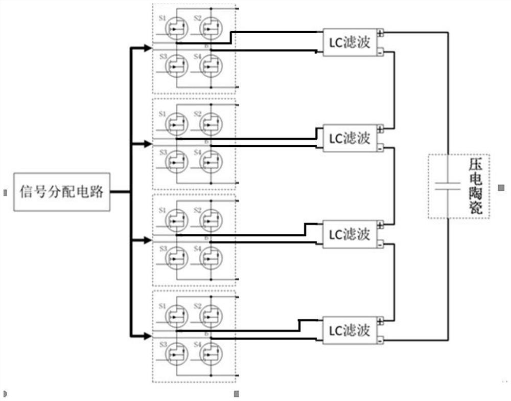
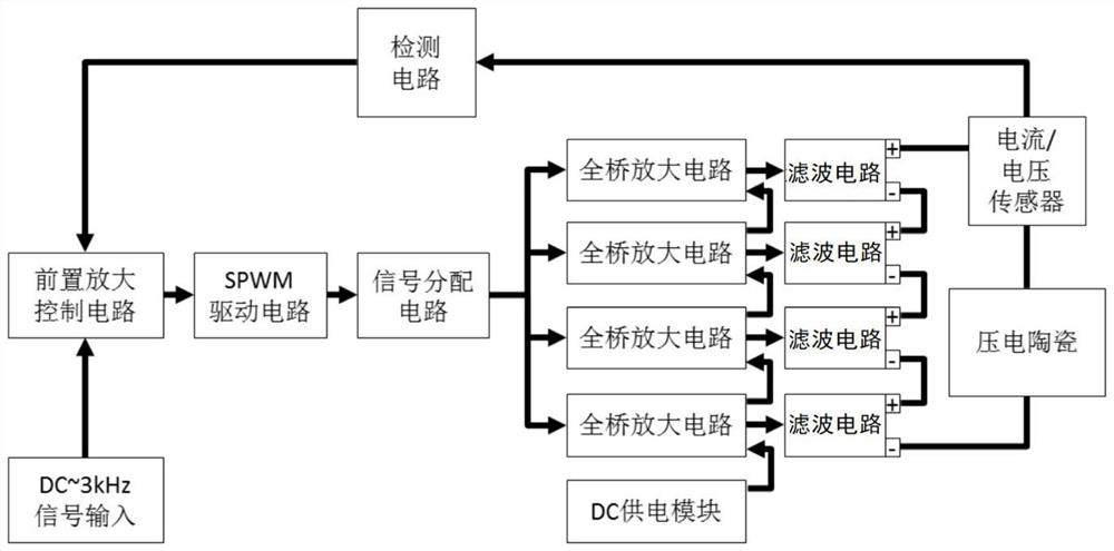
[0013] as attached figure 1 As shown, the present invention is a high-voltage power amplifier for a piezoelectric ceramic vibration platform, including a preamplification control circuit, a SPWM drive circuit, a signal distribution circuit, at least one full-bridge inverter circuit, at least one filter circuit, a sensor and a detection circuit and piezoelectric ceramics; the pre-amplification control circuit is used for signal input; the output end of the pre-amplification control circuit is connected to the input end of the signal distribution circuit through the SPWM drive circuit; the output end of the signal distribution circuit is connected through the full The bridge inverter circuit is connected to the filter circuit; the output end of the filter circuit is connected to the piezoelectric ceramic; the sensor and the detection circuit are connected to the output end of...


PUM


Abstract

The invention discloses a high-voltage power amplifier for a piezoelectric ceramic vibration platform. The high-voltage power amplifier comprises a pre-amplification control circuit, an SPWM drive circuit, a signal distribution circuit, at least one full-bridge inverter circuit, at least one filter circuit, a sensor, a detection circuit and piezoelectric ceramic. A multi-path full-bridge invertercircuit series topological structure is adopted, a core amplifier tube is controlled in an SPWM driving mode, and high voltage, high frequency and large current are generated and output to an equivalent capacitive piezoelectric ceramic load. According to the power amplifier based on the full-bridge switch type topological structure, the matching resistance in a half-bridge structure is reduced, the performance of the vibration platform piezoelectric ceramic amplifier is improved, and high-frequency and high-voltage voltage signals are output at the same time.

Description

technical field [0001] The invention belongs to the technical field of power amplifier drive control, and in particular relates to a high-voltage power amplifier used for a piezoelectric ceramic vibration platform. Background technique [0002] In the application of piezoelectric ceramic vibration platform, the working frequency range of mechanical environment test is usually 5Hz~2000Hz. In order to ensure the expansion and contraction characteristics of piezoelectric ceramics in the high frequency band, the power amplifier of the vibration platform needs to have the output capability of high voltage and high frequency, that is, it can Output high voltage at high frequency. [0003] With the development of power electronics, the DC amplified driving power supply with power operational amplifiers and analog power devices as the core has the advantages of simple principle, easy driving method, and low output ripple. If it is applied to high-voltage, high-frequency, and high-p...

Claims


Application Information

Patent Timeline
IPC IPC(8): H03F3/20H03F1/02
CPCH03F1/02H03F3/20
Inventor 王宇飞代明香王珏毛勇建李晓琳邓婷李明海何建军师伟鹏郭旭军
Owner GENERAL ENG RES INST CHINA ACAD OF ENG PHYSICS
Why Eureka
Eureka Blog
Learn More