High-collision-energy alternating voltage ion dissociation device and mass spectrometry method

A technology of alternating voltage and collision energy, applied in the field of mass spectrometry, can solve the problems of difficult to guarantee accuracy, small storage capacity, high energy, etc., and achieve the effects of low processing and manufacturing cost, strong alternating electric field strength, and improving collision energy.

Pending Publication Date: 2021-01-15
SHANGHAI YUDA IND
View PDF2 Cites 1 Cited by
  • Summary
  • Abstract
  • Description
  • Claims
  • Application Information

AI Technical Summary

Problems solved by technology

The three-dimensional ion trap has high mass resolution, but also has the disadvantage of small storage capacity
However, the arc-shaped electrode rod used in this invention has the problems of high processing difficulty and difficult guarantee of precision.
Moreover, when it is used as a collision reaction cell, the application method of the collision alternating voltage is still the traditional dipole excitation method, and the excitation electric field is still symmetrical about the axis of the expelling direction, so it is still impossible to avoid the ion in a large alternating current. Ejection losses under voltage, with limitations
In the dipole excitation mode, the collision energy of ions is very sensitive to the change of the AC amplitude of the excitation voltage, which can easily cause the energy to be too high and cause the ions to fly out of the trap.
Therefore, the amplitude of the excitation alternating voltage AC is usually set to a small value, which limits the application of many other aspects, such as optimizing the internal alternating excitation electric field by adjusting the magnitude of the alternating voltage AC, etc.
In addition, due to the limitation of AC amplitude, ions gain energy slowly, which causes the problem of low ion collision efficiency.

Method used


Image

  • High-collision-energy alternating voltage ion dissociation device and mass spectrometry method
  • High-collision-energy alternating voltage ion dissociation device and mass spectrometry method
  • High-collision-energy alternating voltage ion dissociation device and mass spectrometry method

Examples


Embodiment 1

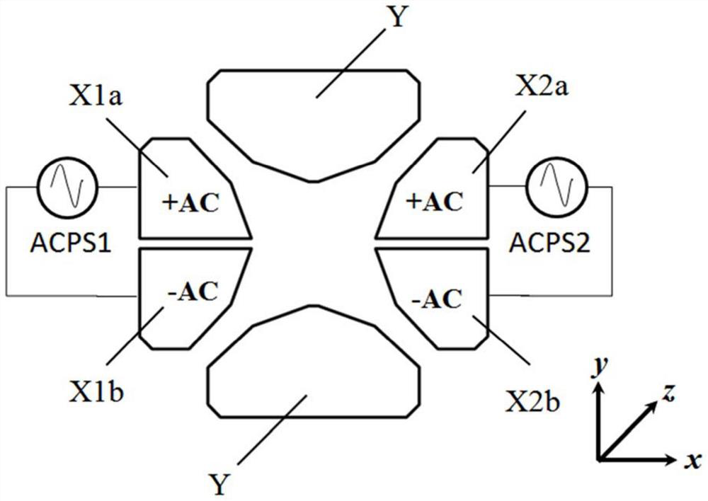
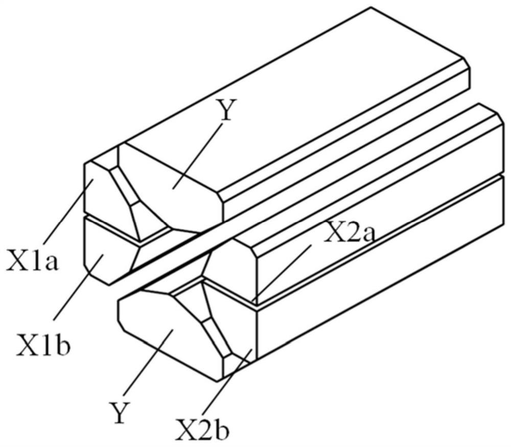
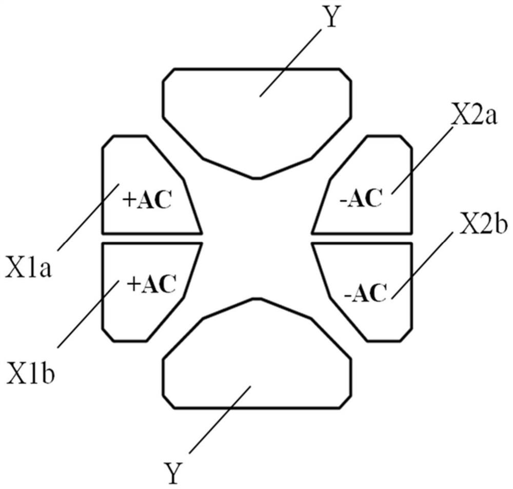
[0039] Such as figure 1 As shown, a high collision energy alternating voltage ion dissociation device is surrounded by a pair of X electrodes and a pair of Y electrodes, and the X electrodes and Y electrodes are triangular electrodes figure 2 is a three-dimensional diagram of the high collision energy alternating voltage ion dissociation device. A pair of X electrodes are each divided into two pieces along the axial center line, respectively X1a and X1b, X2a and X2b. In this embodiment, the high collision energy alternating voltage ion dissociation device is a multi-electrode radio frequency ion storage and analysis device, such as an ion trap mass analyzer. The shape of the X electrode and the Y electrode is a triangle, the angle is 140°, and the field radius (the distance from the top of the electrode to the geometric center of the ion trap) is 5 mm. A radio frequency voltage RF with the same amplitude and 180° phase difference is applied to the X electrode pair and the Y...

Embodiment 2

[0043] Such as Figure 6 As shown, a high collision energy alternating voltage ion dissociation device is surrounded by a pair of X electrodes and a pair of Y electrodes. The X electrodes and Y electrodes are hyperbolic electrodes. Similarly, the The high collision energy alternating voltage ion dissociation device is a multi-electrode radio frequency ion storage and analysis device, that is, an ion trap. Figure 7 is a three-dimensional diagram of the high collision energy alternating voltage ion dissociation device. In this embodiment, the X electrodes and the Y electrodes are hyperboloid electrodes. A pair of X electrodes is divided into two pieces along the axial direction, namely X3a and X3b, X4a and X4b. When working, the X electrode pair and the Y electrode pair apply radio frequency voltage RF with the same amplitude and 180° phase difference for ion capture and trapping. The phase of the first alternating voltage power supply is opposite to that of the alternating ...

Embodiment 3

[0046] Such as Figure 8 As shown, a high collision energy alternating voltage ion dissociation device is surrounded by a pair of X electrodes and a pair of Y electrodes, and the X electrodes and Y electrodes are round rods. Figure 9 is a three-dimensional diagram of the high collision energy alternating voltage ion dissociation device. The X electrodes and Y electrodes in this embodiment are round rods. In this implementation, the high collision energy alternating voltage ion dissociation device is a multi-electrode radio-frequency ion transmission device, that is, a quadrupole. The difference from the above embodiment is that: a pair of X electrodes are divided into two pieces along the axial centerline respectively, X3a and X3b, X4a and X4b respectively; a pair of Y electrodes are respectively divided into two pieces along the axial centerline Two blocks, namely Y3a and Y3b, Y4a and Y4b. The reverse direct current DC and the radio frequency RF with the same amplitude an...


PUM


Abstract

The invention provides a high-collision-energy alternating voltage ion dissociation device and a mass spectrometry method. The device is characterized in that the device comprises a pair of X electrodes which are parallel to each other, a pair of Y electrodes which are parallel to each other and a pair of end cover electrodes; and the X electrode pair and the Y electrode pair are parallel to eachother and have equal distances to the geometric center of the device. The at least one pair of electrodes is divided into two electrodes in the axial direction (the z direction is perpendicular to thexy plane). The phases of alternating voltages applied to the two electrodes on one side by a first alternating voltage power supply are opposite; and a second alternating voltage power supply appliesalternating voltage with the same or opposite phase as the output signal of the first alternating voltage power supply to the two electrodes on the other side. According to the high-collision-energyalternating ion dissociation device and method, the structure is simple, the machining and manufacturing cost is low, and the voltage applying mode is easy to achieve.

Description

technical field [0001] The invention relates to the technical field of mass spectrometry, in particular to a high collision energy alternating voltage ion dissociation device and a mass spectrometry analysis method. Background technique [0002] Mass spectrometry is an analytical method for analyzing the composition of substances by measuring the mass-to-charge ratio of the measured sample ions. The sample to be tested is first ionized, and then the ions are separated according to the mass-to-charge ratio (m / z) to obtain a mass spectrum by using the different motion behaviors of different ions in the electric field or magnetic field. By analyzing the mass spectrum, the qualitative and quantitative results of the sample can be obtained. [0003] Ion trap mass spectrometer has the characteristics of fast analysis speed, high sensitivity and excellent analysis performance, especially suitable for tandem mass spectrometry analysis, and has been widely used in the field of molec...

Claims


Application Information

Patent Timeline
Patent Type & Authority Applications(China)
IPC IPC(8): H01J49/00
CPCH01J49/0063
Inventor 姚如娇蒋公羽朱勇勇何洋庞骏德郭锡岩沈辉陈元景加荣
Owner SHANGHAI YUDA IND
Why Eureka
Try Eureka