Eureka AIR delivers breakthrough ideas for toughest innovation challenges, trusted by R&D personnel around the world.

Graphite electrode resistivity detection device

A technology for detecting devices and graphite electrodes, which is applied to measuring devices, measuring resistance/reactance/impedance, measuring electrical variables, etc., can solve the problems of lack of graphite electrode fixing, lower detection efficiency, rolling position offset, etc., to achieve convenient storage, Improve detection efficiency and prevent electric shock

Active Publication Date: 2021-01-29
滁州市技术监督检测中心
View PDF5 Cites 0 Cited by
  • Summary
  • Abstract
  • Description
  • Claims
  • Application Information

AI Technical Summary

Problems solved by technology

[0006] The object of the present invention is to provide a kind of graphite electrode resistivity detection device, to solve the above-mentioned background technology proposed in the existing graphite electrode resistivity detection device, the general detection method is to place the graphite electrode on the detection platform with insulating pad The electrode is charged on the top, and the voltage value is obtained after multiple measurements to obtain the result, and the process of handling the graphite electrode is generally manual handling, which will cause damage to the graphite electrode during manual handling, and manual handling back and forth will consume energy and increase Large labor costs, and the lack of fixing of graphite electrodes on the general detection table, which will lead to the phenomenon of rolling position deviation during the early detection process, causing inconvenience of detection and reducing the detection efficiency

Method used

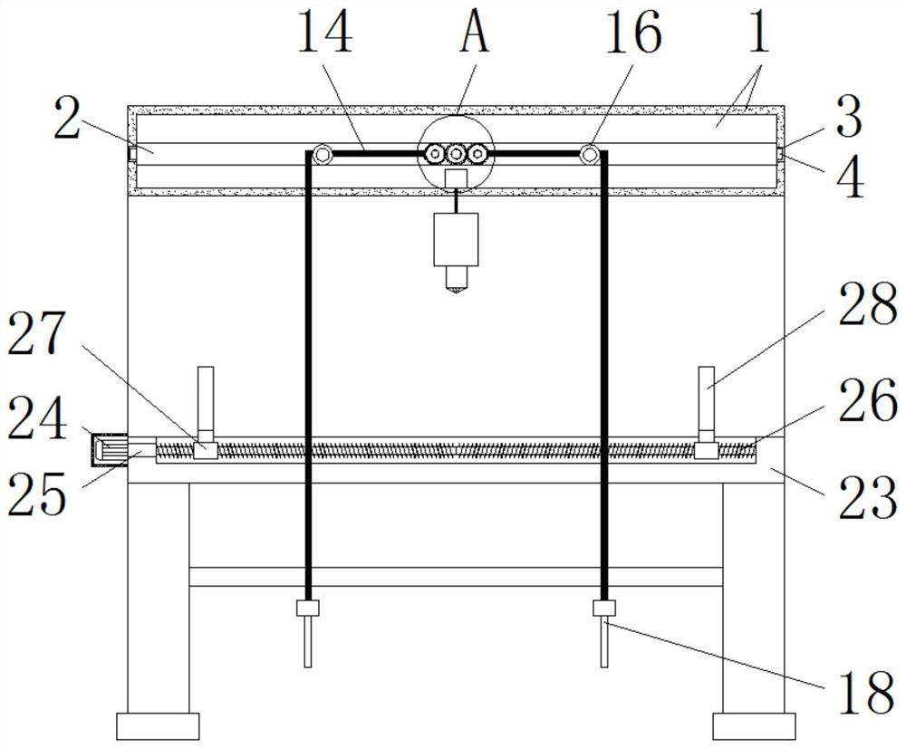

Image

  • Graphite electrode resistivity detection device
  • Graphite electrode resistivity detection device
  • Graphite electrode resistivity detection device

Examples


Embodiment Construction

[0028] The following will clearly and completely describe the technical solutions in the embodiments of the present invention with reference to the accompanying drawings in the embodiments of the present invention. Obviously, the described embodiments are only some, not all, embodiments of the present invention. Based on the embodiments of the present invention, all other embodiments obtained by persons of ordinary skill in the art without making creative efforts belong to the protection scope of the present invention.

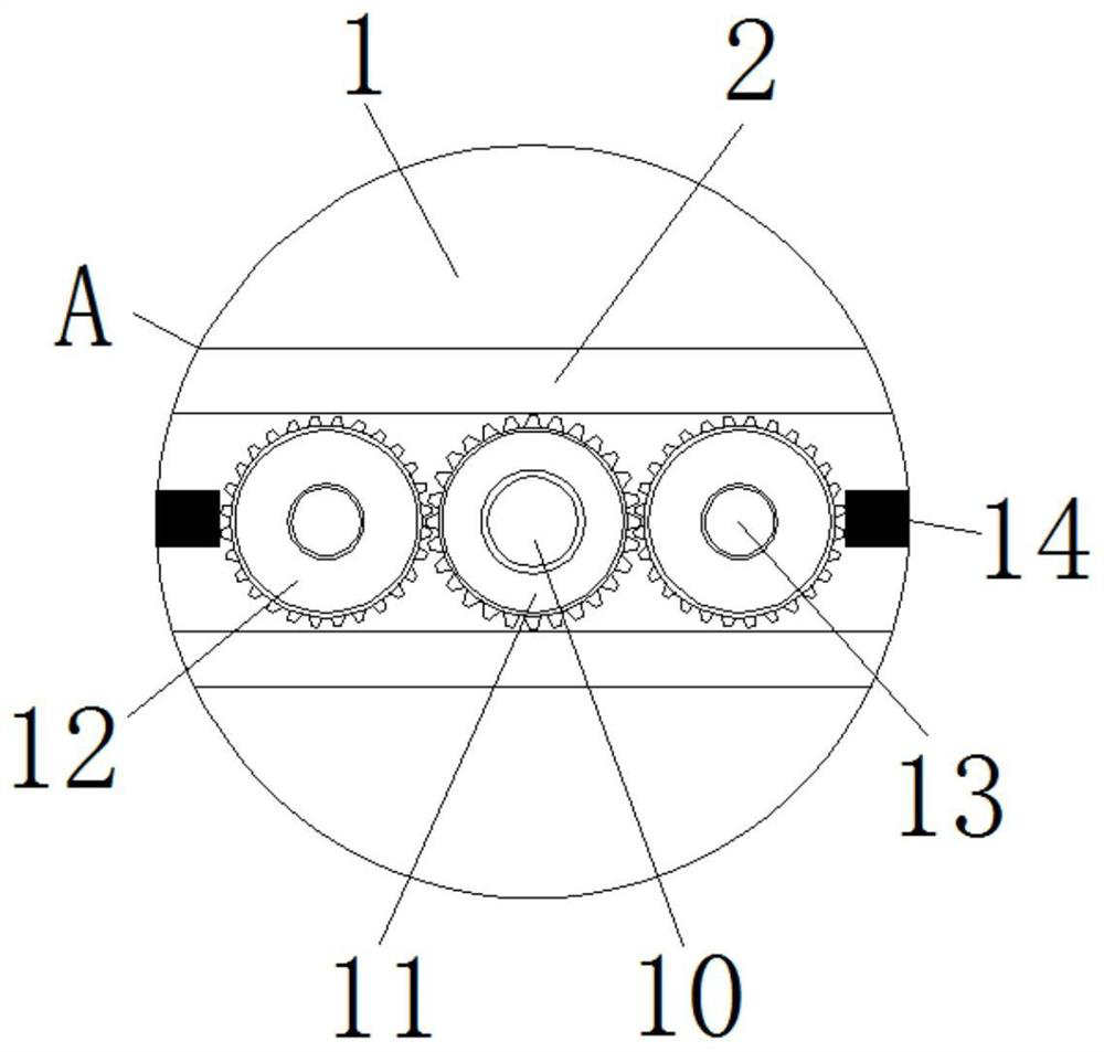
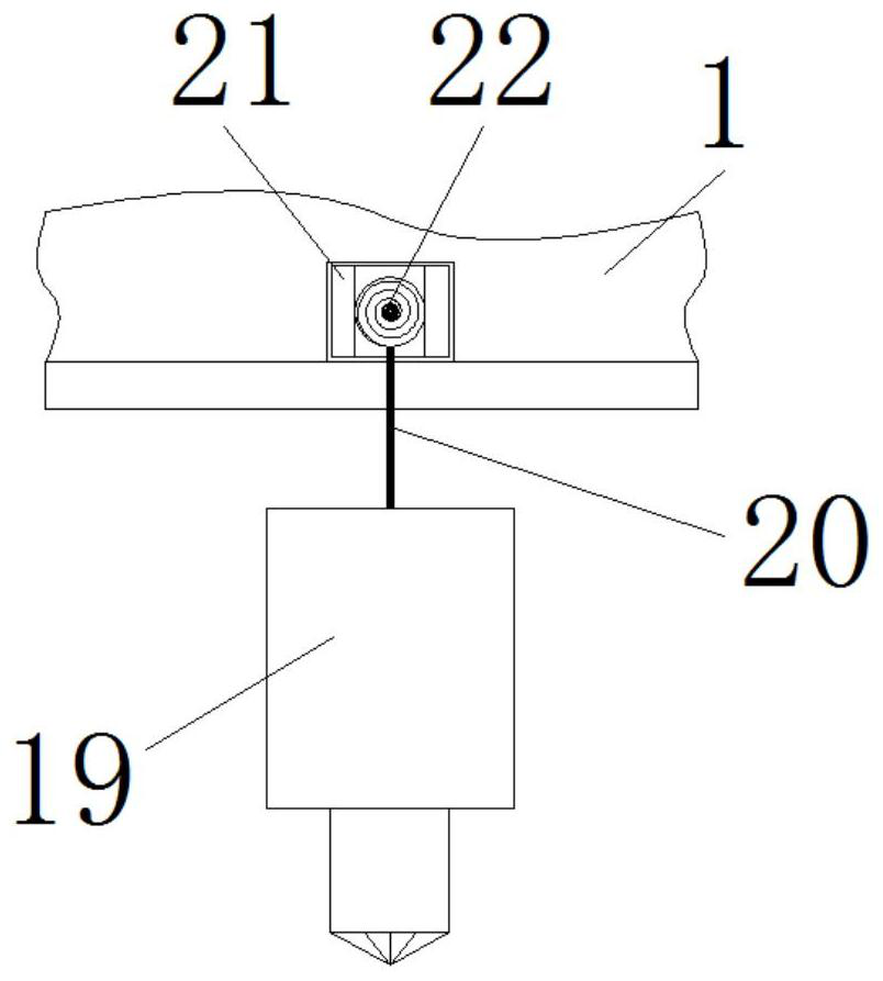
[0029] see Figure 1-7 , the present invention provides a technical solution: a graphite electrode resistivity detection device, comprising a hanging plate 1, a drive motor 9 and a detection platform 23, the inside of the hanging plate 1 is provided with a slide bar 2, and the inside of the hanging plate 1 is provided with The chute 3, the inside of the chute 3 is connected with a slide plate 4, and the slide plate 4 is installed on the outside of the slide ba...


PUM


Abstract

The invention discloses a graphite electrode resistivity detection device, and the device comprises an upper hanging plate, a driving motor and a detection table, a sliding rod is arranged in the upper hanging plate, a sliding groove is formed in the upper hanging plate, a sliding plate is connected in the sliding groove, the sliding plate is installed outside the sliding rod, and a poking rod isarranged outside the upper hanging plate; the bottom of the poke rod is connected with a connecting rod, the connecting rod is located in the upper hanging plate, a positioning rod is arranged outsidethe connecting rod, and the positioning rod is located in the upper hanging plate. According to the graphite electrode resistivity detection device, the two sleeve rods sleeving the screw rod relatively move through the threads in the opposite directions on the two sides, and the sleeve rods move to drive the clamping rings to move, so that the wide distance between the clamping rings can be conveniently adjusted according to the size of a graphite electrode, and the graphite electrode can be conveniently fixed by the clamping rings; and the graphite electrode does not deviate during detection, so that the detection efficiency is improved.

Description

technical field [0001] The invention relates to the technical field of graphite electrodes, in particular to a graphite electrode resistivity detection device. Background technique [0002] Graphite electrodes are mainly made of petroleum coke and needle coke, and coal tar pitch is used as a binder. They are made by calcination, batching, kneading, pressing, roasting, graphitization, and machining. They are released in the form of arcs in electric arc furnaces. Graphite is very common in nature, and graphene is the strongest substance known to human beings. The resistivity contained in graphite electrodes is a physical quantity used to represent the resistance characteristics of various substances. The ratio of the product of the resistance and the cross-sectional area to the length of the original made of the substance is called the resistivity of the substance, and the graphite electrode is a conductor of the resistivity. [0003] 1. In the existing graphite electrode res...

Claims


Application Information

Patent Timeline
Patent Type & Authority Applications(China)
IPC IPC(8): G01R27/02
CPCG01R27/02
Inventor 陈旭娟
Owner 滁州市技术监督检测中心
Why Eureka
Eureka Blog
Learn More