Ventricular drainage-pressure control system

A ventricular drainage and pressure control technology, applied in wound drainage devices, intracranial pressure measurement, sensors, etc., can solve the problem of inability to accurately adjust and control the drainage pressure of the drainage tube, increase the workload of medical staff, unable to strictly control the drainage speed of the drainage tube, and Drainage and other issues, to avoid manual rotation of the three-way valve, controllable drainage, and reduce intracranial infection.

Inactive Publication Date: 2021-02-05
张军
View PDF11 Cites 1 Cited by
  • Summary
  • Abstract
  • Description
  • Claims
  • Application Information

AI Technical Summary

Problems solved by technology

It is impossible to strictly control the drainage speed and drainage volume of the drainage tube, and it is impossible to accurately adjust and control the drainage pressure of the drainage tube, and each pressure measurement is realized by manually switching the three-way valve, which increases the workload of medical staff

Method used


Image

  • Ventricular drainage-pressure control system
  • Ventricular drainage-pressure control system
  • Ventricular drainage-pressure control system

Examples


Embodiment 1

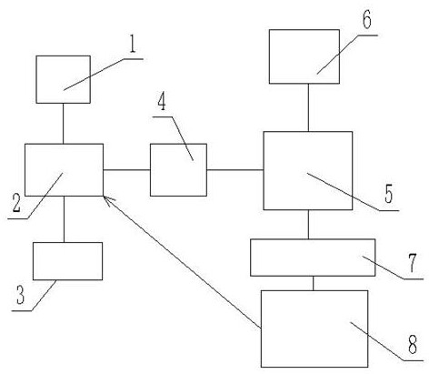
[0029] see Figure 1-5 , a ventricle drainage-pressure control system, comprising a pressure sensor 4 and a ventricle drainage tube 1, the pressure sensor 4 and the ventricle drainage tube 1 are connected to the same electromagnetic three-way valve 2, the pressure sensor 4 is connected to a splitter 5, divided The splitter 5 is a one-to-two interface, and the splitter 5 is respectively connected with the ECG monitor 6 and the pressure data branch line 7, and the front end of the pressure data branch line 7 is connected with a pressure measurement and control module 8, and the pressure measurement and control module 8 It is also directly connected with the electromagnetic three-way valve 2.

[0030] Further, the solenoid valve three-way valve is also connected with a drainage bag 3 .

[0031] When in use, the ventricle drainage tube 1 is placed in the ventricle to drain the cerebrospinal fluid, and the electromagnetic three-way valve 2 is connected with the ventricle drainage ...

Embodiment 2

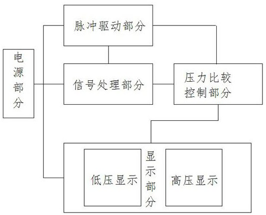
[0037] refer to Figure 6 , 7 , on the basis of Embodiment 1, the display part includes a low-voltage display and a high-voltage display. The low-voltage display includes a chip U11, an amplifier U9A and a display module DS1. The chip U11 is also connected with a rheostat VRZ5 and a variable resistor R56. The high-voltage display includes Chip U12, amplifier U13A and display module DS2, amplifier U13A is also connected with rheostat VRZ6 and variable resistance R58, U11 samples the set reference before hysteresis action and keeps displaying, U12 samples the setting reference before hysteresis action and keeps displaying.


PUM


Abstract

The invention discloses a ventricular drainage-pressure control system. The ventricular drainage-pressure control system comprises a pressure sensor and a ventricular drainage tube, wherein the pressure sensor and the ventricular drainage tube are connected with the same electromagnetic three-way valve, a deconcentrator is connected to the pressure sensor, the deconcentrator has a one-to-two interface, and an electrocardiogram monitor and a pressure data branch line are respectively connected to the deconcentrator; and a pressure measuring and adjusting module is connected to the front end ofthe pressure data branch line, and is also directly connected with the electromagnetic three-way valve. The system has the advantages that the operation is automatic, manual rotation of the three-wayvalve is avoided, the intracranial infection is reduced, the workload of medical personnel is reduced, the intermittent drainage is realized, and the risk caused by the continuous drainage at presentis avoided.

Description

technical field [0001] The invention relates to medical equipment, in particular to a ventricle drainage-pressure control system. Background technique [0002] Continuous ventricle drainage is the name of a medical operation. It is suitable for patients with severe intracranial pressure such as intraventricular or posterior fossa space-occupying lesions, frequent vomiting, weakness, and vision loss. Continuous drainage of the ventricles can be performed first, and then proceed after the condition improves. Angiography and surgery still require drainage for several days after surgery. [0003] At present, the measurement of intracranial pressure by connecting the arterial or venous pressure sensor through the ventricular drainage tube has been proved to have certain clinical significance. In simple drainage, the drainage speed and drainage volume are controlled by adjusting the height of the drainage tube, and the intracranial pressure is measured by manually controlling the...

Claims


Application Information

Patent Timeline
Patent Type & Authority Applications(China)
IPC IPC(8): A61M27/00A61B5/03H03K3/26H03K17/60
CPCA61M27/006A61B5/031H03K3/26H03K17/60A61M2205/3331
Inventor 张军
Owner 张军
Why Eureka
Try Eureka