
Magnetic field detection method based on magnetic dielectric effect, test device and working method thereof

A test device, electric effect technology, applied in the direction of measuring device, size/direction of magnetic field, magnetic field measurement using electromagnetic devices, etc., can solve the problems of high cost and many limitations of magnetoelectric induction sensors, and achieve low cost, The effect of high resolution and simple circuit structure

Pending Publication Date: 2021-02-05
ZHENGZHOU UNIVERSITY OF LIGHT INDUSTRY
View PDF0 Cites 5 Cited by
  • Summary
  • Abstract
  • Description
  • Claims
  • Application Information

AI Technical Summary

Problems solved by technology

[0004] Aiming at the technical problems that current magnetoelectric induction sensors with coil structure have many limitations and relatively high cost, the present invention proposes a magnetic field detection method based on the magnetodielectric effect, a test device and its working method. The overall preparation process is simple and the price is low. It is cheap, and has the advantages of high magnetic field detection sensitivity and strong mobile flexibility, and has potential application value in the field of weak magnetic field detection

Method used


Image

  • Magnetic field detection method based on magnetic dielectric effect, test device and working method thereof
  • Magnetic field detection method based on magnetic dielectric effect, test device and working method thereof
  • Magnetic field detection method based on magnetic dielectric effect, test device and working method thereof

Examples


Embodiment 1

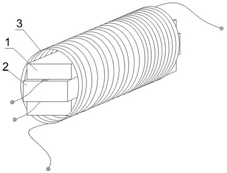
[0030] Embodiment 1: as figure 1 As shown, a method for detecting a magnetic field based on the magnetodielectric effect comprises the following steps:

[0031] S1. Keep the magnetoelectric composite structure detector consistent with the direction of the magnetic field to be measured along the length direction. The magnetoelectric composite structure detector is a magnetoelectric composite structure composed of spinel ferrite and piezoelectric ceramics. The variable magnetic field is captured by the ferrite material to generate mechanical strain at the same frequency, which is then transmitted to the piezoelectric ceramic material through interlayer coupling, and finally output as a capacitive signal to realize the detection of the AC magnetic field.

[0032] The magnetoelectric composite structure detector is a "sandwich" type three-layer structure. The magnetoelectric composite structure detector includes two layers of magnetostrictive material on the upper and lower layers...

Embodiment 2

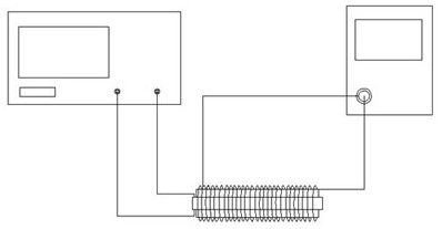
[0036] Embodiment 2: as figure 2 As shown, a test device for detecting a magnetic field based on the magnetodielectric effect includes a signal generator, an AC coil, a magnetoelectric composite structure detector and an impedance analyzer. The AC coil 3 is wound on the magnetoelectric composite structure detector, and the AC coil 3 Both ends are connected to the signal generator, and the magnetoelectric composite structure detector is connected to the impedance analyzer. The magnetoelectric composite structure detector is a strain-mediated multi-layer heterogeneous block structure, and the magnetoelectric composite structure detector is Ni 0.8 Zn 0.2 Tb 0.02 Fe 1.98 o 4 -PZT-Ni 0.8 Zn 0.2 Tb 0.02 Fe 1.98 o 4 A three-layer magnetoelectric composite structure detector, the magnetoelectric composite structure detector includes two layers of terbium-doped nickel zinc ferrite magnetostrictive material and a layer of PZT-8 piezoelectric ceramic material, two layers of magn...

Embodiment 3

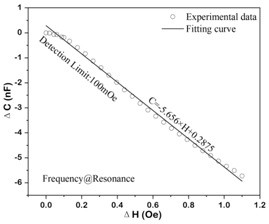
[0038] Embodiment 3: as Figure 3~5 Shown, the working method of the test device based on magnetodielectric effect detection magnetic field is characterized in that, comprises the following steps:

[0039] A1, apply high-frequency current to the AC coil through the signal generator to form a high-frequency AC magnetic field as the magnetic field to be measured, and the magnetostrictive layer in the magnetoelectric composite structure detector will sense the magnetic field generated by the coil and generate it along the length direction The strain force, the transmitted stress acts on the piezoelectric ceramic material layer through the interface coupling, so that the dielectric constant of the piezoelectric material changes, and the capacitance signal is derived from two wires drawn from the upper and lower plates of the piezoelectric material, which is consistent with the piezoelectric material The dielectric constant is directly proportional, and this direct magnetodielectri...


PUM

PropertyMeasurementUnit
Sensitivityaaaaaaaaaa

Abstract

The invention provides a magnetic field detection method based on magnetic dielectric effect, a test device and a working method thereof. The test device comprises a magnetoelectric composite detection structure, the magnetoelectric composite detection structure is formed by laminating spinel ferrite and piezoelectric ceramic, and a to-be-detected alternating magnetic field is captured by a ferrite material and then generates mechanical strain with the same frequency as excitation. And then the mechanical strain is transmitted to a piezoelectric ceramic material through interlayer coupling andfinally output in a capacitance signal mode, detection of an alternating-current magnetic field is achieved, and an impedance analyzer is used for scanning a capacitance spectrum of a magnetoelectriccomposite detection structure to complete measurement of typical sensing parameters such as sensitivity and resolution of a magnetic sensing device. Compared with a traditional electromagnetic sensorinduction detection mode, the method gets rid of the limitation of an external bias magnetic field, improves the detection sensitivity, is not liable to be interfered by an external power frequency signal, the signal-to-noise ratio is higher, and the overall device is more compact.

Description

technical field [0001] The invention relates to the technical field of AC magnetic field methods, in particular to a magnetic field detection method based on magnetodielectric effects, a test device and a working method thereof. Background technique [0002] Since the British Michael Faraday discovered the law of electromagnetic induction in 1831, people have been exploring and researching magnetic fields more and more deeply. Magnetic sensors play an irreplaceable role in the application and transformation of traditional industries, resource exploration and comprehensive utilization, environmental protection, bioengineering, intelligent traffic control and other fields. The advantages of magnetic sensing technology are particularly evident in robotics and factory automation. Common applications include fuel gauges that detect floats in automotive fuel tanks, and magnetic sensing devices used to detect the rotor position of brushless motors. At the same time, various magnet...

Claims


Application Information

Patent Timeline
Patent Type & Authority Applications(China)
IPC IPC(8): G01R33/06
CPCG01R33/063
Inventor 张吉涛刘嘉晖张庆芳武洁陶加贵张培任林娇姜利英曹玲芝
Owner ZHENGZHOU UNIVERSITY OF LIGHT INDUSTRY
Learn More