Anti-slag-adhering laser pipe cutting machine and cut pipe collecting method

A tube cutting machine and laser technology, applied in laser welding equipment, tubular items, applications, etc., can solve the problems of damage to the tube, splashing of waste residue, falling of the tube to the ground or the receiving car, etc., to achieve low cost and improve the finished product. Quality, the effect of reducing scratches and collision damage

Inactive Publication Date: 2021-02-09
JINAN SENFENG TECH CO LTD
View PDF6 Cites 8 Cited by
  • Summary
  • Abstract
  • Description
  • Claims
  • Application Information

AI Technical Summary

Problems solved by technology

[0004] In order to overcome the deficiencies in the above-mentioned prior art, the present invention provides an anti-slag laser pipe cutting machine to solve the problem that the waste slag splashes when the pipe is cut and the pipe directly falls to the ground or the receiving vehicle after processing to cause damage to the pipe. question

Method used


Image

  • Anti-slag-adhering laser pipe cutting machine and cut pipe collecting method
  • Anti-slag-adhering laser pipe cutting machine and cut pipe collecting method
  • Anti-slag-adhering laser pipe cutting machine and cut pipe collecting method

Examples


Embodiment approach 1

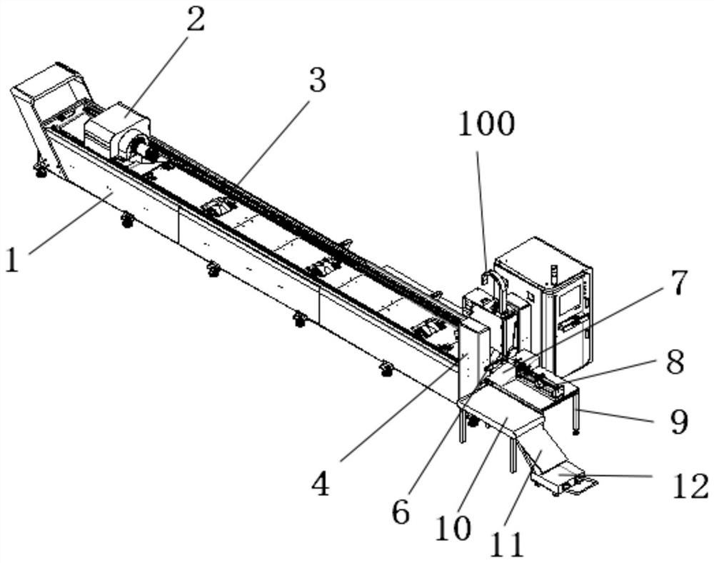
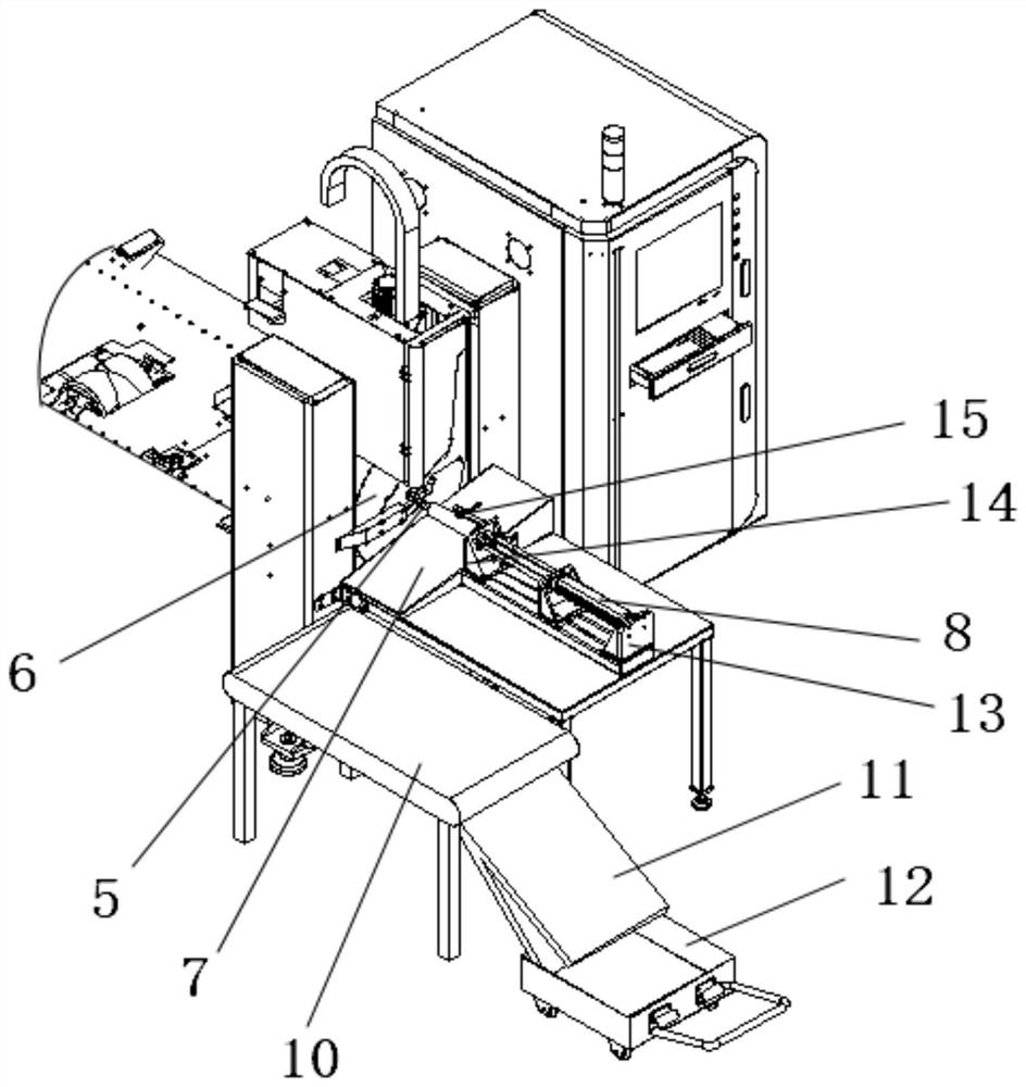
[0038] Such as Figure 1-Figure 8As shown, this specific embodiment provides an anti-dross laser pipe cutting machine, including a cutting bed 1, a waste slag collection mechanism, an underframe 9, a pipe conveying mechanism, a blanking buffer mechanism, and a material receiving device 12. The cutting bed 1 is provided with a gantry 4, a cutting head assembly 100, a front chuck 6 and a rear chuck 2, and the gantry 4 is provided with a transverse guide rail, the cutting head assembly 100 is installed on the transverse guide rail and can slide along the transverse guide rail, the cutting bed The body 1 is provided with a longitudinal guide rail, the rear chuck 2 is slidably installed on the longitudinal guide rail, the front chuck 6 is installed on the cutting bed 1 and is located at the position of the gantry frame 4; the waste residue collection mechanism is installed on the chassis 9 and Close to the front chuck 6, the waste slag collection mechanism includes a slender slag r...

specific Embodiment approach 2

[0043] This specific embodiment provides a method for collecting anti-slag cutting pipes, including the anti-slag laser pipe cutting machine in Embodiment 1, and also includes the following steps:

[0044] A1: Turn the variable-diameter lifting roller 3 according to the pipe specification, and place the pipe on the variable-diameter lifting roller 3;

[0045] A2: The rear chuck 2 moves forward to hold the tail end of the pipe, and the front chuck 6 holds the front end of the pipe;

[0046] A3: The slag receiving pipe 5 extends into the pipe, and the slag receiving hole 51 on the slag receiving pipe 5 is located directly below the cutting head. The cutting head cuts the pipe, and the waste slag during the cutting process falls into the slag receiving pipe 5;

[0047] A4: After the pipe is cut, the pipe falls onto the slag receiving pipe 5, and the sensor switch 15 senses the signal and feeds back to the system, and the slag receiving pipe 5 drives the cut pipe to retract;

[0...


PUM


Abstract

The invention provides an anti-slag-adhering laser pipe cutting machine and a cut pipe collecting method. The anti-slag-adhering laser pipe cutting machine comprises a cutting machine body, a waste slag collecting mechanism, a bottom frame, a pipe conveying mechanism, a material falling buffer mechanism and a material receiving device. The cutting machine body is provided with a portal frame, a cutting head assembly, a front chuck and a rear chuck. The waste slag collecting mechanism is installed on the bottom frame and close to the front chuck. The waste slag collecting mechanism comprises along and thin slag receiving pipe and a telescopic driving mechanism, a slag receiving hole is formed in the side wall of the front portion of the slag receiving pipe, a protective layer is arranged in the slag receiving pipe, and the rear portion of the slag receiving pipe is connected with the telescopic driving mechanism. A material falling slope is arranged on the bottom frame, the material falling slope is located below the slag receiving pipe, the pipe conveying mechanism is located between the material falling slope and the material falling buffer mechanism, and the material falling buffer mechanism is located above the material receiving device. The problems that at present, waste slag splashes during pipe cutting, and machined pipes directly fall onto the bottom face or a materialcollecting trolley and are prone to being damaged are solved.

Description

technical field [0001] The invention relates to the field of laser cutting equipment, in particular to a slag-preventing laser pipe cutting machine and a cutting pipe collection method. Background technique [0002] Laser cutting is that the laser beam emitted by the laser is focused by the lens, and it is gathered into a very small spot at the focal point. When the spot is irradiated on the material, the material is quickly heated to the vaporization temperature, and evaporates to form holes. With the help of auxiliary gas (such as CO2, O2, N2, etc.) to blow away the molten slag, the holes are continuously formed into a narrow slit to complete the cutting of the material. When cutting pipes, the waste slag blown away by the auxiliary gas after high-temperature melting will splash on the inner wall of the pipe in a divergent shape, affecting the quality of the pipe, especially now that more and more industries have higher precision requirements for the inner wall of the pipe...

Claims


Application Information

Patent Timeline
Patent Type & Authority Applications(China)
IPC IPC(8): B23K26/38B23K26/142B23K26/70
CPCB23K26/38B23K26/142B23K26/702B23K2101/06
Inventor 王翠萍位颜红王庆伟
Owner JINAN SENFENG TECH CO LTD
Why Eureka
Try Eureka