
Mid-infrared laser based on ring cavity mixing end pump pulse output

A pulse output and laser technology, applied in lasers, laser parts, semiconductor lasers, etc., can solve the difficulty of obtaining high repetition frequency, high peak power mid-infrared pulsed laser at the same time, difficult to ensure high output power and high beam quality at the same time, It is difficult to obtain high beam quality laser output and other problems, so as to reduce the internal thermal effect, improve the comprehensive conversion efficiency, and improve the thermal effect.

Active Publication Date: 2021-02-09
CHANGCHUN UNIV OF SCI & TECH
View PDF15 Cites 0 Cited by
  • Summary
  • Abstract
  • Description
  • Claims
  • Application Information

AI Technical Summary

Problems solved by technology

[0004] (1) Electro-optic, acousto-optic, saturable absorption, mechanical and other Q-switches are difficult to simultaneously obtain high repetition frequency, high peak power, and narrow pulse width mid-infrared pulsed laser in the 2.7-3.0μm band
[0005] (2) It is difficult to ensure high output power and high beam quality at the same time
Using flash lamp and semiconductor laser side pumping, although the obtained laser output power is high, but the matching of the side pumping mode is relatively poor, it is difficult to obtain high beam quality laser output
Using a semiconductor laser to pump one end of an Er:YSGG crystal, the mode of the generated oscillating light matches the pumping light mode well, so that the quality of the generated laser pulse beam is high, but the injection energy of the pumping light is limited, thus resulting in lower output laser power
[0006] (3) Solve the problem of side-pumping Er:Cr:YSGG crystals with flash lamps in the prior art to generate more harmful heat; solve the problems that Er:YSGG crystals have low absorption coefficient for 970nm semiconductor laser and low light-to-light conversion efficiency

Method used


Image

  • Mid-infrared laser based on ring cavity mixing end pump pulse output
  • Mid-infrared laser based on ring cavity mixing end pump pulse output

Examples


Embodiment 1

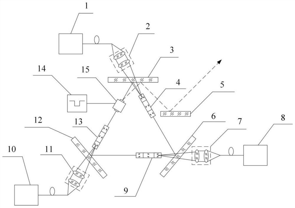
[0041] Example 1: A mid-infrared laser with a ring cavity mixed-end pump pulse output, such as figure 1 As shown, it includes a first semiconductor laser 1, a second semiconductor laser 8, a third semiconductor laser 10, a first coupling lens group 2, a second coupling lens group 7, a third coupling lens group 11, a first dichroic mirror 3, The second dichromatic mirror 6 , the third dichromatic mirror 12 , the first composite crystal 4 , the second composite crystal 9 , the third composite crystal 13 , the total reflection mirror 5 , the high-frequency oscillation power supply 14 and the acousto-optic Q-switch 15 .

[0042] The first semiconductor laser 1, the second semiconductor laser 8 and the third semiconductor laser 10 are respectively a 970nm semiconductor laser, a 654nm semiconductor laser and a 450nm semiconductor laser, and the first semiconductor laser 1, the second semiconductor laser 8 and the third semiconductor laser 10 emit The light respectively passes throug...

Embodiment 2

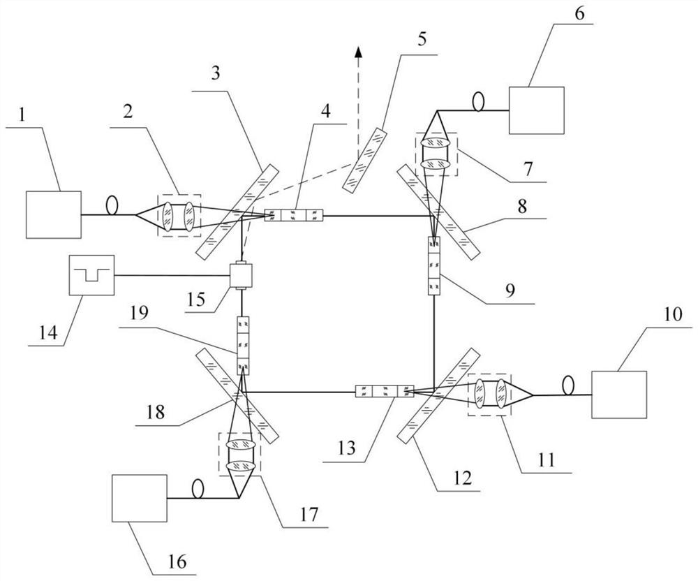
[0047] Embodiment 2: A mid-infrared laser with a ring cavity mixed-end pump pulse output, such as figure 2 As shown, it includes a first semiconductor laser 1, a second semiconductor laser 8, a third semiconductor laser 10, a fourth semiconductor laser 16, a first coupling lens group 2, a second coupling lens group 7, a third coupling lens group 11, The fourth coupling lens group 17, the first dichroic mirror 3, the second dichroic mirror 6, the third dichroic mirror 12, the fourth dichroic mirror 18, the first composite crystal 4, the second composite crystal 9, the third composite crystal Crystal 13 , fourth composite crystal 19 total reflection mirror 5 , high frequency oscillation power supply 14 and acousto-optic Q-switch 15 .

[0048] The fourth semiconductor laser 16 is a 654nm semiconductor laser, and by increasing the number of 654nm semiconductor lasers, the injection power of the 654nm pump light is increased.

[0049] The light emitted by the first semiconductor ...


PUM


Abstract

The invention relates to the field of mid-infrared lasers, in particular to a mid-infrared laser based on ring cavity mixing end pump pulse output. The mid-infrared laser comprises a plurality of pumping devices, two adjacent pumping devices are arranged according to a preset angle, and each pumping device comprises a semiconductor laser and coupling lens groups; a composite crystal is arranged atone side of each coupling lens group, dichroic mirrors are arranged between the coupling lens groups and the composite crystals, and the plurality of dichroic mirrors form an annular resonant cavity;an acousto-optic Q-switch is positioned between the composite crystal and the dichroic mirror and is arranged along the propagation direction of an oscillation light beam in the annular resonant cavity, and a total reflective mirror is positioned in a light path reflected by the dichroic mirror. The invention provides the mid-infrared laser based on the ring cavity mixing end pump pulse output, and solves the problem that the existing mid-infrared laser is difficult to obtain pulse laser with high repetition frequency, narrow pulse width, high power and high beam quality.

Description

technical field [0001] The invention relates to the field of mid-infrared lasers, in particular to a mid-infrared laser based on ring cavity mixed-end pump pulse output. Background technique [0002] The mid-infrared laser in the 2.7-3.0μm band is at the absorption peak of water, which can excite the high-speed kinetic energy of water molecules. It is used as a scalpel in the fields of ophthalmology, dentistry, orthopedics. In order to reduce the damage of laser to surrounding soft tissues, laser The pulse width should be as small as possible less than the thermal relaxation time of the soft tissue. In addition, the mid-infrared laser in the 2.7-3.0 μm band is a high-quality pump source for pumping nonlinear crystals to generate 8-13 μm mid- to long-infrared lasers. Laser pulses with high repetition frequency and high peak power can improve conversion efficiency. [0003] The problems with existing lasers are: [0004] (1) Electro-optic, acousto-optic, saturable absorption...

Claims


Application Information

Patent Timeline
Patent Type & Authority Applications(China)
IPC IPC(8): H01S5/10H01S5/0625H01S5/042H01S5/0225H01S5/00H01S5/30
CPCH01S5/005H01S5/0085H01S5/0428H01S5/06253H01S5/1003H01S5/30
Inventor 李永亮杨亚帅王驰张英明吴起通张晗
Owner CHANGCHUN UNIV OF SCI & TECH
Learn More