
Transmission gate circuit and resistance adjusting circuit using transmission gate circuit

A transmission gate circuit and transmission gate technology, applied in circuits, electrical components, electronic switches, etc., can solve problems such as affecting the reliability of the device and the transmission gate cannot be completely turned off, so as to improve the reliability of work and reduce the risk of withstand voltage of the device. , Overcome the effect of not being able to turn off completely

Pending Publication Date: 2021-02-09
成都思瑞浦微电子科技有限公司
View PDF0 Cites 0 Cited by
  • Summary
  • Abstract
  • Description
  • Claims
  • Application Information

AI Technical Summary

Problems solved by technology

However, when the voltage at both ends of A and B is continuously switched according to the high and low voltage of the working state, the transmission gate may not be completely turned off, and it faces the risk of device withstand voltage, which affects the reliability of the device.

Method used


Image

  • Transmission gate circuit and resistance adjusting circuit using transmission gate circuit
  • Transmission gate circuit and resistance adjusting circuit using transmission gate circuit

Examples


Embodiment Construction

[0013] The specific implementation of the present invention will be described in further detail below in conjunction with the accompanying drawings of the embodiments, so as to make the technical solution of the present invention easier to understand and grasp, so as to define the protection scope of the present invention more clearly.

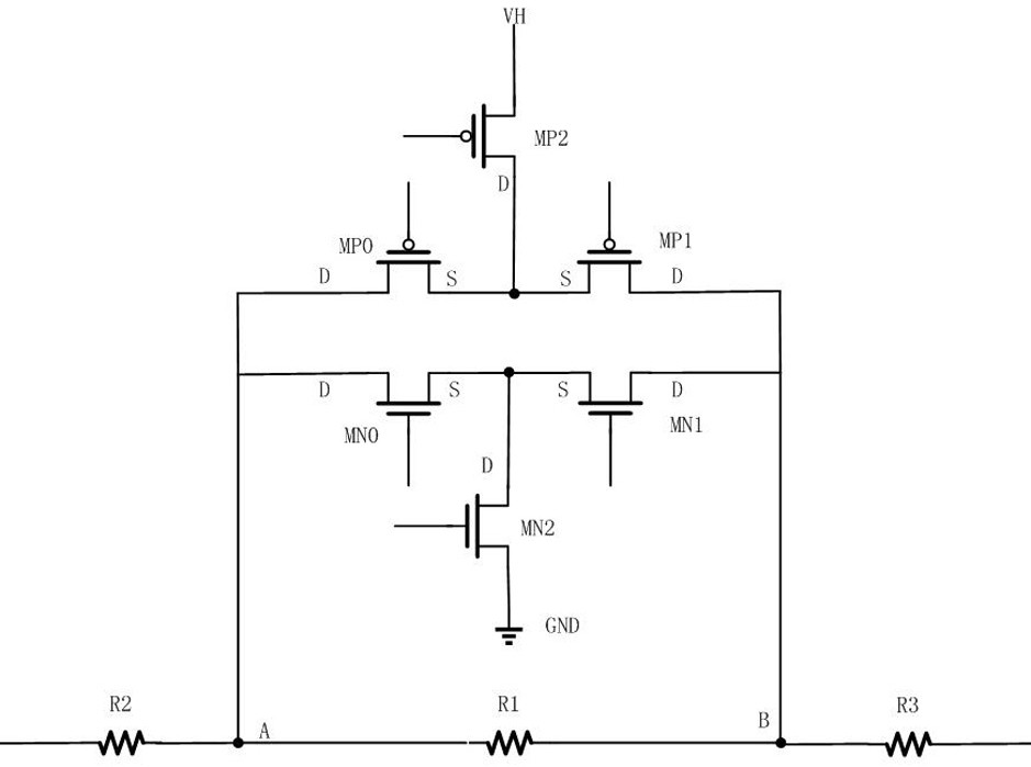
[0014] The designer of the present invention made a comprehensive analysis on the deficiencies such as the ordinary transmission gate may not be able to be completely turned off under the control of different voltage domains, the device faces the risk of withstand voltage, and the reliability is poor. Combining his own experience and creative labor, he proposed a transmission The improved structure of the gate circuit and the resistance adjustment circuit using the transmission gate. On the basis of ordinary transmission gates, device configuration and connection are optimized to ensure that the transmission gates can be completely turned on or...


PUM


Abstract

The invention discloses a transmission gate circuit and a resistance adjusting circuit using the transmission gate, the transmission gate is formed by connecting NMOS tubes and PMOS tubes, the commonsource electrodes of the PMOS tubes MP0 and MP1 are connected with the drain electrode of a normal-voltage PMOS pull-up tube MP2, the source electrode of the pull-up tube MP2 is connected with the highest voltage VH of the circuit, and the common source electrodes of the NMOS tubes MN0 and MN1 are connected with the drain electrode of the normal-voltage NMOS tubes. The common drain electrode of the PMOS tube MP0 and the NMOS tube MN0 is a node A, the common drain electrode of the PMOS tube MP1 and the NMOS tube MN1 is a node B, the transmission gate is completely switched off or completely switched on along with the adjustment of the grid electrodes of the PMOS tube MP0 and the PMOS tube MP1 and the grid electrodes of the NMOS tube MN0 and the NMOS tube MN1, and is connected in parallel with the resistor for shielding or retaining the resistor. By applying the improved transmission gate design provided by the invention, the problem that the voltages at the two ends cannot be completelyturned off when being switched along with high and low voltages is effectively solved, the voltage withstanding risk of the device is reduced, and the working reliability of an application device ofthe whole transmission gate is improved.

Description

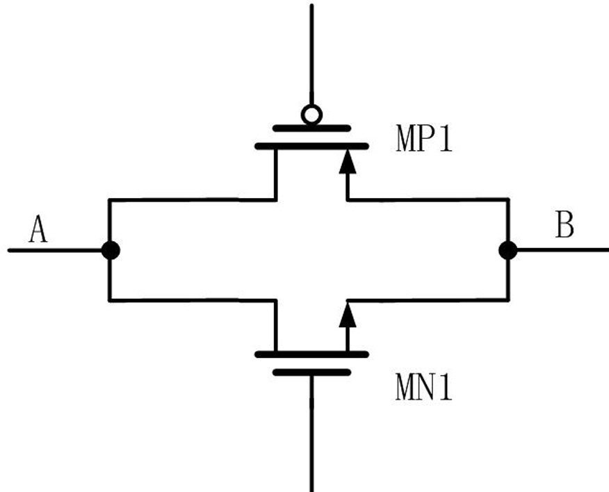
technical field [0001] The invention relates to an improved structure of a transmission gate circuit, in particular to a transmission gate circuit with more complete functions for parallel connection with a resistor to adjust resistance and related applications, and the applied resistance adjustment circuit. Background technique [0002] In the design of the audio chip, it is necessary to set the signal gain amplitude of different gears for the audio input signal in different scene modes according to the customer application, so as to adjust the sound level heard by the human ear. In circuit implementation, it is usually realized by adjusting the resistance value of the feedback resistor of the audio system. Usually, in circuit implementation, the value of the feedback resistance is changed through the parallel connection of the transmission gate and the resistance. Such as figure 1 Shown is a common transmission gate formed by connecting a PMOS transistor MP1 and an NMOS ...

Claims


Application Information

Patent Timeline
IPC IPC(8): H03K17/06H03K17/08H03G3/30
CPCH03G3/3005H03K17/063H03K17/08
Inventor 何均
Owner 成都思瑞浦微电子科技有限公司
Learn More