Method for optimizing microscopic structure of steel rail welding joint
A technology for welded joints and microstructures, which is applied in the field of rail welding, can solve problems such as abnormal microstructures, and achieve remarkable results, simple process flow, and convenient operation
- Summary
- Abstract
- Description
- Claims
- Application Information
AI Technical Summary
Problems solved by technology
Method used
Image

Examples
Embodiment 1
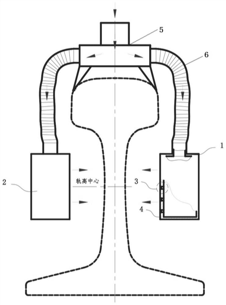
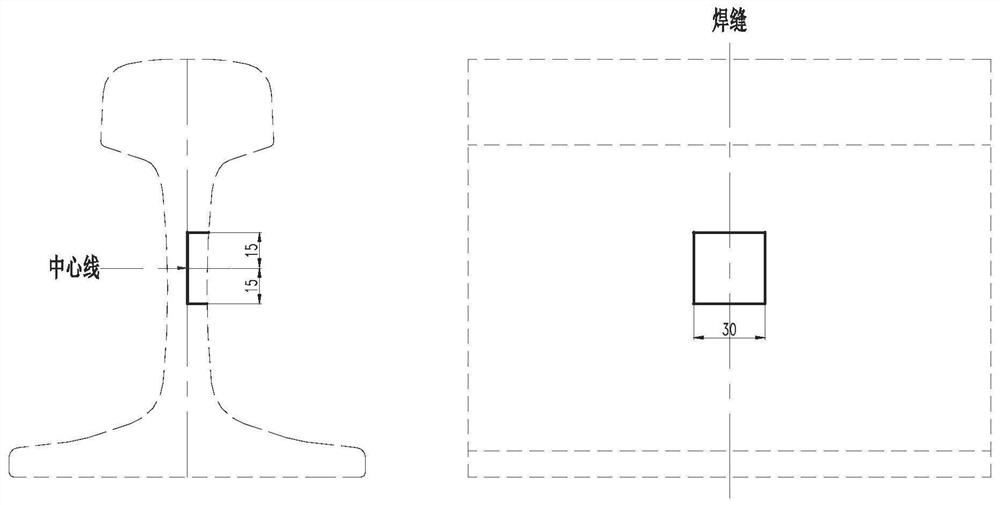
[0064] The experimental material of this embodiment is the 68kg rail profile and rail head hardened (heat-treated) pearlitic rail specified in the AS 1085.1: Railway track materials, Part 1: Steelrails standard, and the measured carbon content of the physical chemical composition of the rail is 0.8% by weight. Carry out 5 parallel experiments, the specific experimental process includes the following steps: use GAAS80 / 580 rail fixed flash welding welding machine to carry out welding experiments, use accelerated cooling device 2 (cooling surface 4 is 15mm away from the rail waist surface, and the spray angle is 110 °), using Compressed air (with a pressure of 0.4MPa) is used as the cooling medium to accelerate the cooling of the rail waist of the welded joint to be cooled by flash welding. At the same time, an infrared thermometer is used to measure the temperature of the center of the weld seam of the welded joint rail waist and continuously monitor it. Temperature, the cooling ...
Embodiment 2
[0066] The experimental material of this embodiment is the 68kg rail profile and rail head hardened (heat-treated) pearlitic rail specified in the AS 1085.1: Railway track materials, Part 1: Steelrails standard, and the measured carbon content of the physical chemical composition of the rail is 0.8% by weight. Carry out 5 parallel experiments, the specific experimental process includes the following steps: adopt rail mobile flash welding machine to carry out welding experiment, use accelerated cooling device 2 (cooling surface 4 is apart from rail waist surface 15mm, spray angle is 110 °), adopt compressed air ( The pressure is 0.4MPa) as the cooling medium to accelerate the cooling of the welded joint rail waist part to be cooled by flash welding. The cooling rate at the center of the waist weld is 19-35°C / s. When the temperature drops to 1000°C, the control system automatically shuts off the cooling medium, immediately stops the accelerated cooling, and then places the joint ...
Embodiment 3
[0074]The experimental materials in this example are the 60E1 rail profile specified in the BS EN 13674-1: Railway applications–Track–Rail, Part 1: Vignole railway rails 46kg / m and above standard, the R260 hot-rolled pearlitic rail, and the rail solid chemistry Composition The measured carbon content was 0.6% by weight. Carry out 5 parallel experiments, the specific experimental process includes the following steps: adopt rail mobile flash welding machine to carry out welding experiment, use accelerated cooling device 2 (cooling surface 4 is apart from rail waist surface 30mm, spray angle is 115 °), adopt compressed air ( The pressure is 0.6MPa) as the cooling medium to accelerate the cooling of the rail waist of the welded joint to be cooled by flash welding. The cooling rate at the center of the waist weld is 19-35°C / s. When the temperature drops to 900°C, the control system automatically shuts off the cooling medium, immediately stops the accelerated cooling, and then place...
PUM
 Abstract
Description
Claims
Application Information
 - R&D Engineer
- R&D Manager
- IP Professional
- Industry Leading Data Capabilities
- Powerful AI technology
- Patent DNA Extraction
Browse by: Latest US Patents, China's latest patents, Technical Efficacy Thesaurus, Application Domain, Technology Topic.
© 2024 PatSnap. All rights reserved.Legal|Privacy policy|Modern Slavery Act Transparency Statement|Sitemap