
Hazardous waste rotary kiln incineration process

A rotary kiln and hazardous waste technology, applied to incinerators, combustion methods, combustion types, etc., can solve problems such as heat loss, low air excess coefficient, low heat loss rate, etc., to achieve reduced heat loss, low air excess system , the effect of increasing the combustion rate

Active Publication Date: 2021-02-12
XINZHONGTIAN ENVIRONMENTAL PROTECTION
View PDF5 Cites 3 Cited by
  • Summary
  • Abstract
  • Description
  • Claims
  • Application Information

AI Technical Summary

Problems solved by technology

[0004]Usually, when hazardous waste is incinerated in a rotary kiln, the air flowing into the rotary kiln cannot be sufficiently diffused, and the formed flow field is not fully covered, and along the axis of the rotary kiln If the moving speed is too high, etc., it will lead to the increase of thermal ignition loss rate, that is, the full combustion of hazardous waste cannot be guaranteed. The current common practice is to increase the air supply, but this will make the air excess coefficient of the rotary kiln too high, resulting in heat loss. For example, the current common rotary kiln incineration process will open an air hole on the top of the kiln hood, and use the air hole for air supply. In order to ensure that the thermal ignition loss rate is within the range of 5% to 8%, the rotary kiln The air excess coefficient has reached 1.5-2.0, so the current process cannot ensure a low thermal ignition loss rate and a low air excess coefficient at the same time

Method used


Image

  • Hazardous waste rotary kiln incineration process
  • Hazardous waste rotary kiln incineration process
  • Hazardous waste rotary kiln incineration process

Examples


Embodiment 1

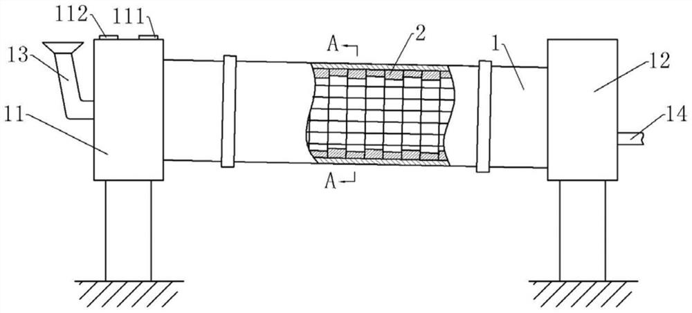
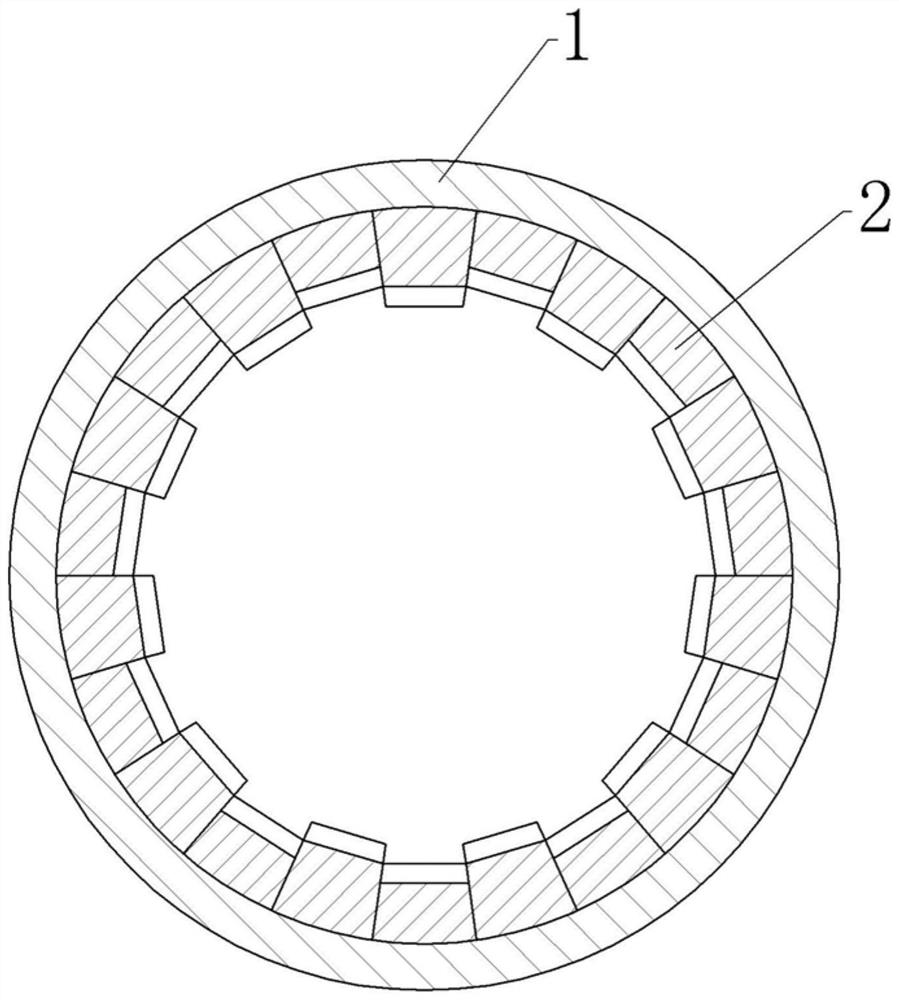
[0040]The incineration process of hazardous waste rotary kiln is realized by using hazardous waste rotary kiln. Hazardous waste rotary kiln is basically as attachedfigure 1 As shown, it includes a support frame and a cylinder 1 rotatably connected to the support frame. The cylinder 1 is inclined downwards from left to right. The inclination angle of the cylinder 1 is set according to actual needs. In this embodiment, the cylinder 1 The tilt angle is 10°. The support frame is also fixed with a motor, the drive shaft of the motor is coaxially fixed with a driving gear, and the cylinder 1 is coaxially fixed with a driven ring gear meshing with the driving gear, so the motor can drive the driving gear to rotate, and through the slave The transmission of the movable gear ring realizes the rotation of the cylinder 1.

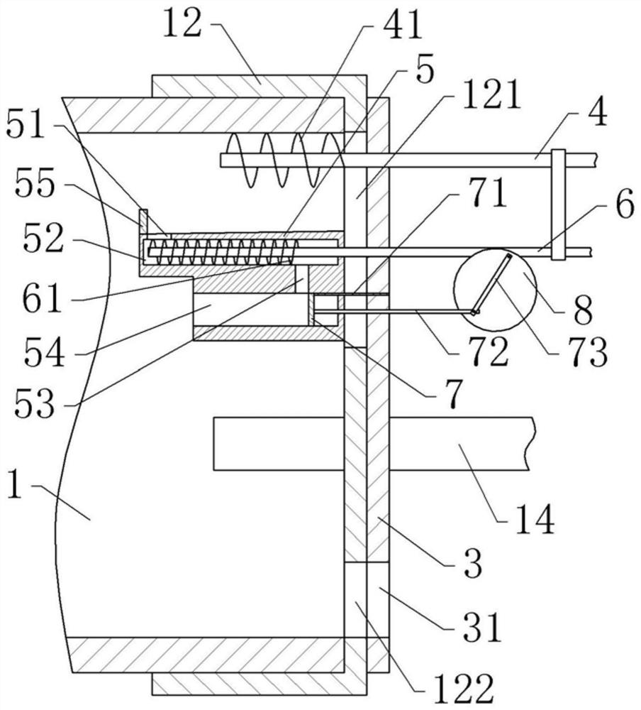
[0041]The left end of the cylinder 1 is rotatably connected with a kiln head cover 11, and the right end of the cylinder 1 is rotatably connected with a kiln tail cover 12. A ...

Embodiment 2

[0064]The difference between embodiment 2 and embodiment 1 is only that, asFigure 5 As shown, in this embodiment, each material dispersion structure includes 8 groups of 2 groups of refractory bricks, and each group of 2 groups of refractory bricks includes one higher refractory brick 2 and three lower refractory bricks 2. The higher refractory brick 2 The height difference between the lower refractory brick 2 and the lower refractory brick 2 is 50mm or 100mm. This embodiment is preferably 50mm, and the adjacent higher refractory bricks 2 are the lower refractory bricks 2; that is, the structure of each material is dispersed Refractory bricks 2 are set in cycles of a, a, a, a+50mm, a...a+50mm, a, a, a, a+50mm.

[0065]CombineFigure 4 As shown, each group of material dispersion structure in this embodiment includes a higher material dispersion structure and three lower material dispersion structures. The height difference between the higher material dispersion structure and the lower ma...

Embodiment 3

[0068]The only difference between Example 3 and Example 1 is that D=1.5d in this example; through model simulation calculations, a conclusion similar to Example 1 is reached, that is, the excess air coefficient of hazardous waste incineration is controlled within 0.8~ 1.0 to control the air supply, the rotary kiln's hazardous waste incineration heat loss rate is less than 3%.


PUM


Abstract

The invention belongs to the technical field of hazardous waste incineration, and discloses a hazardous waste rotary kiln incineration process which is realized by adopting a hazardous waste rotary kiln. The hazardous waste rotary kiln comprises a cylinder body, the two ends of the cylinder body are respectively provided with a kiln head cover and a kiln tail cover in a rotatably and hermeticallyconnected manner, the lower part of the kiln tail cover is provided with a slag outlet, and the kiln head cover is cylindrical; a main air hole and an auxiliary air hole are formed in the side wall ofthe kiln head cover, the main air hole is located in the top of the kiln head cover, the main air hole and the auxiliary air hole are not located in the same circumferential line of the kiln head cover, the main air hole is formed close to the cylinder body, and the auxiliary air hole is formed in the side away from the cylinder body; hazardous waste is thrown into the cylinder body to be incinerated, after the temperature in the cylinder body rises to 1000-1150 DEG C, air is supplied into the kiln head cover from the main air hole and the auxiliary air hole, and the air speed of the main airhole and the air speed of the auxiliary air hole are consistent; and after the hazardous waste is incinerated, ash slag is guided out from the slag outlet. By means of the hazardous waste rotary kilnincineration process, it can be guaranteed that the ignition loss rate is low after hazardous waste is incinerated, and the excess air coefficient is low, so that the hazardous waste can be fully incinerated, and heat losses in the incineration process can be reduced.

Description

Technical field[0001]The invention belongs to the technical field of hazardous waste incineration, and specifically relates to a hazardous waste rotary kiln incineration process.Background technique[0002]Hazardous waste is the abbreviation of hazardous waste, which refers to wastes that are listed in the national hazardous waste list or identified according to the hazardous waste identification standards and identification methods prescribed by the state with hazardous waste characteristics. Most of the hazardous waste contains toxic and harmful substances, which will pollute the environment if discharged at will, so it usually needs to be treated before being discharged.[0003]Nowadays, rotary kilns are usually used to incinerate hazardous waste, and then the incineration ash is discharged. The heat loss rate of the ash after incineration is the most powerful basis for judging whether the rotary kiln is normal or not, and can calculate the completion status of the incineration.[0004...

Claims


Application Information

Patent Timeline
Patent Type & Authority Applications(China)
IPC IPC(8): F23G7/00F23G5/20F23G5/44F23J1/06
CPCF23G7/00F23G5/20F23G5/44F23J1/06F23G2203/20
Inventor 林辉荣胡茂丽杨贵林黄泽华邓波
Owner XINZHONGTIAN ENVIRONMENTAL PROTECTION
Learn More