
Electroslag remelting production system

A production system and electroslag remelting technology, applied in the field of electroslag remelting equipment, can solve the problems of fluid loss of heat exchange and cooling effect, insufficient use of cooling water, poor cooling effect, etc., to improve heat exchange and cooling. effect, increased flow disorder, improved cooling effect

Pending Publication Date: 2021-02-23
淄博秦鼎昌特钢科技有限公司
View PDF0 Cites 0 Cited by
  • Summary
  • Abstract
  • Description
  • Claims
  • Application Information

AI Technical Summary

Problems solved by technology

[0003] However, the existing equipment has the following deficiencies: 1. The traditional production method is to replace the consumable electrode rod with a new one at the chuck after the consumable electrode rod is consumed, and continue the electroslag remelting work
Since the installation of new electrode rods takes a certain amount of time, resulting in intermittent production and reduced production efficiency
2. There is flowing cold water between the inner and outer cylinders of the electroslag remelting crystallizer for cooling, and the cooling water flows from the bottom to the top, so that the water cooling chamber is filled with cooling water, but the outer cylinder of the existing crystallizer There is a water inlet and a water outlet respectively on the top, such a setting is easy to produce a fluid dead angle, so that the fluid in a certain part of the water cooling chamber flows slowly or even does not flow, and this part of the fluid loses the effect of heat exchange and cooling, and the circulating cooling water is If it is not fully utilized, the cooling efficiency is low, the cooling effect is not good, and the product quality is greatly affected

Method used


Image

  • Electroslag remelting production system
  • Electroslag remelting production system
  • Electroslag remelting production system

Examples


Embodiment Construction

[0029] The present invention will be further described below in conjunction with embodiment:

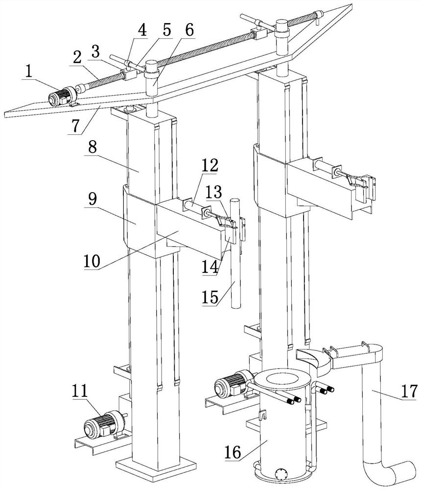
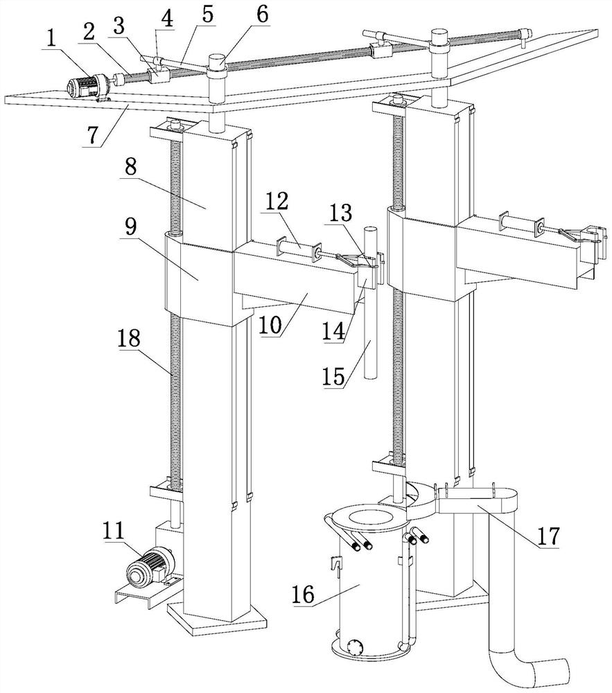
[0030] Such as Figure 1-11 As shown, the electroslag remelting production system of the present invention includes an electrode lifting mechanism and a crystallizer 16. The electrode lifting mechanism is provided in two groups, which are respectively arranged on the left and right sides of the crystallizer 16. The electrode lifting mechanism The mechanism includes a column 8, which is provided with a liftable electrode clamping mechanism. The column 8 is rotatably arranged between the frame 7 on the top and the base at the bottom, and the columns 8 on both sides rotate synchronously.

[0031] The top of the column 8 is provided with a rotating shaft 6 fixedly connected to the column 8; the frame 7 is provided with a rotating motor 1, and the rotating motor 1 is connected to drive the traversing screw 2, and the traversing screw 2 is provided with a traversing slider 3, and The slid...


PUM


Abstract

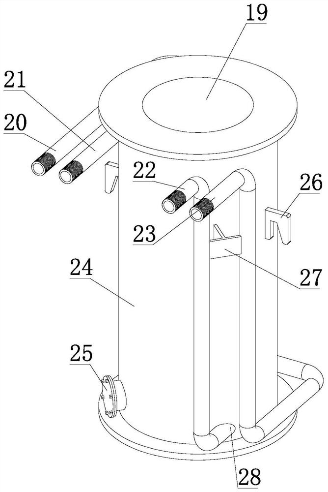
The invention belongs to the technical field of electroslag remelting equipment, and specifically relates to an electroslag remelting production system. The electroslag remelting production system comprises electrode lifting mechanisms and a crystallizer; two sets of electrode lifting mechanisms are provided and arranged on the left and right sides of the crystallizer, respectively; each electrodelifting mechanism comprises a stand column; a liftable electrode clamping mechanism is arranged on each stand column; each stand column is rotatably arranged between a frame at the top and a base atthe bottom; and the stand columns on the two sides rotate synchronously. The stand columns on the two sides are alternately located at an electroslag remelting station and a clamping station, and continuous work can be implemented. By means of the crystallizer in the system, when cooling water flows through a water cooling cavity of the crystallizer, the disorder and flowing disorder of fluid areincreased to avoid fluid dead corners, and cooling water ways are evenly distributed, so that the circulating cooling water is fully utilized, the cooling efficiency is high, the cooling effect is good, the product quality is greatly improved, and the production requirement is met.

Description

technical field [0001] The invention relates to an electroslag remelting production system, belonging to the technical field of electroslag remelting equipment. Background technique [0002] Electroslag remelting is a method of smelting using the resistance heat generated when the current passes through the slag as a heat source. Its purpose is to increase the purity of the metal and improve the crystallization of the ingot. Electroslag remelting steel is more and more widely used for its good quality and high service life, especially in aerospace and various military products, and it has also been widely used in civil industry in recent years . During remelting, the consumable electrode rod is fixed on the cross arm of the electrode lifting mechanism, and the chuck on the cross arm clamps the consumable electrode and inserts it into the slag pool; the consumable electrode, slag pool, metal molten pool, ingot, The bottom water tank forms a loop through a short network cab...

Claims


Application Information

Patent Timeline
Patent Type & Authority Applications(China)
IPC IPC(8): C22B9/187C22B9/193
CPCC22B9/18
Inventor 秦雷
Owner 淄博秦鼎昌特钢科技有限公司
Learn More