
Optical lens, optical lens forming die and manufacturing method thereof

A technology for forming molds and optical lenses, which is applied in optics, lenses, optical components, etc., can solve problems such as uneven quality, affecting optical transmission paths, and difficult processing, and achieves the effects of simple manufacturing process, uniform dispersion of light beams, and simple structure

Active Publication Date: 2021-02-23
ORANGETEK CORP
View PDF12 Cites 0 Cited by
  • Summary
  • Abstract
  • Description
  • Claims
  • Application Information

AI Technical Summary

Problems solved by technology

However, the vortex phase plate is not easy to manufacture, and the conventional optical communication module needs to assemble multiple optical elements to complete the layout of the optical path. The slight deviation of the installation position of each optical element will greatly affect the transmission path of the optical path, and it is difficult to accurately The alignment and processing are not easy and the quality is different, which leads to poor transmission effect

Method used


Image

  • Optical lens, optical lens forming die and manufacturing method thereof
  • Optical lens, optical lens forming die and manufacturing method thereof
  • Optical lens, optical lens forming die and manufacturing method thereof

Examples


Embodiment Construction

[0036] The following examples illustrate possible implementations of the present invention, but are not intended to limit the protection scope of the present invention.

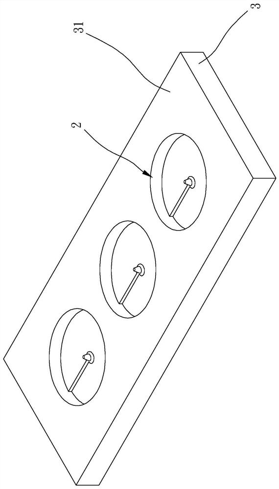
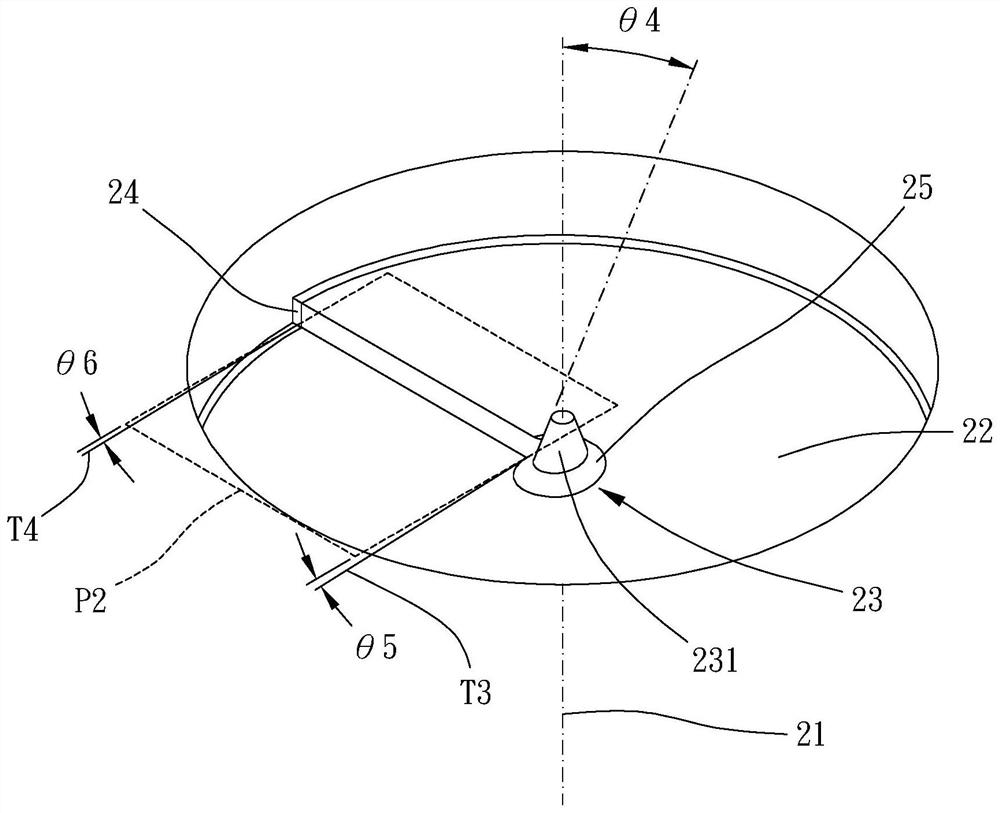
[0037] Please refer to Figures 1 to 5 , which shows a molding die 2 for manufacturing the following optical lens according to a preferred embodiment of the present invention, which includes a helical surface 22 spiraling around an axial direction 21 and an intermediate structure wound by the helicoidal surface 22 23 , the intermediate structure 23 of the molding die 2 extends axially toward one side relative to the helical surface 22 of the molding die 2 , and the helical surface 22 of the molding die 2 goes around to form a first step difference 24 .

[0038] In this embodiment, the intermediate structure 23 of the molding die 2 is a convex column, and the diameter of the end surface of the convex column is greater than or equal to 0.001 mm and less than or equal to 0.02 mm; the intermediate structure 23 of...


PUM

PropertyMeasurementUnit
Arc radiusaaaaaaaaaa
Diameteraaaaaaaaaa
First angleaaaaaaaaaa

Abstract

The invention relates to an optical lens, an optical lens forming die and a manufacturing method thereof. The optical lens comprises a spiral surface which is spirally wound around an axial directionand a middle structure which is spirally wound by the spiral surface, the middle structure axially extends towards one side relative to the spiral surface, and the spiral surface bypasses to form a step difference. The structures of the die and the optical lens are correspondingly complementary. The manufacturing method of the forming die comprises the following steps of providing a base body, wherein the base body includes a processing surface; and processing the processing surface to form the spiral surface, the middle structure and the step difference of the forming die. According to the optical lens, the optical lens forming die and the manufacturing method thereof, the structure is simple, the manufacturing process is simple, the light beams are uniformly dispersed, the machining precision is good, and miniaturization is facilitated.

Description

technical field [0001] The invention relates to an optical lens, an optical lens molding die and a manufacturing method thereof. Background technique [0002] Optical fiber communication has the advantages of good transmission efficiency, resistance to electromagnetic interference and high stability. Optical fiber can be divided into single-mode optical fiber and multi-mode optical fiber according to the transmission mode. The diameter of multi-mode optical fiber is much larger than the wavelength of the beam, so it allows beams of different wavelengths and phases to continuously reflect and transmit along the surrounding wall of the optical fiber. After long-distance transmission There will be a difference in propagation speed between different modes, resulting in modal dispersion and excessively high light flux in the center of the fiber, thereby limiting the transmission distance. [0003] In order to solve the aforementioned problems, a vortex phase plate is generally u...

Claims


Application Information

Patent Timeline
IPC IPC(8): G02B3/00B29C33/00B29C33/42
CPCG02B3/00G02B3/0031B29C33/00B29C33/42
Inventor 陈俊傑张家荣黄智义叶俊毅
Owner ORANGETEK CORP
Learn More