High-CO-concentration flue gas coupling low-temperature SCR temperature control method and system

A temperature control method and flue gas technology, applied in the field of flue gas purification, can solve problems affecting the denitrification reaction process, flue gas temperature fluctuations, etc.

Active Publication Date: 2021-02-26
ZHONGYE-CHANGTIAN INT ENG CO LTD
View PDF10 Cites 0 Cited by
  • Summary
  • Abstract
  • Description
  • Claims
  • Application Information

AI Technical Summary

Problems solved by technology

However, with the change of flue gas volume, original flue gas temperature, CO concentration in flue gas, other components in flue gas, etc., the heat production process of CO catal

Method used


Image

  • High-CO-concentration flue gas coupling low-temperature SCR temperature control method and system
  • High-CO-concentration flue gas coupling low-temperature SCR temperature control method and system
  • High-CO-concentration flue gas coupling low-temperature SCR temperature control method and system

Examples


Embodiment 1

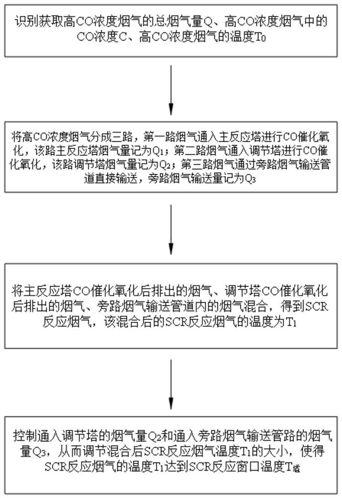
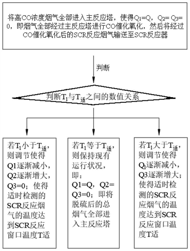
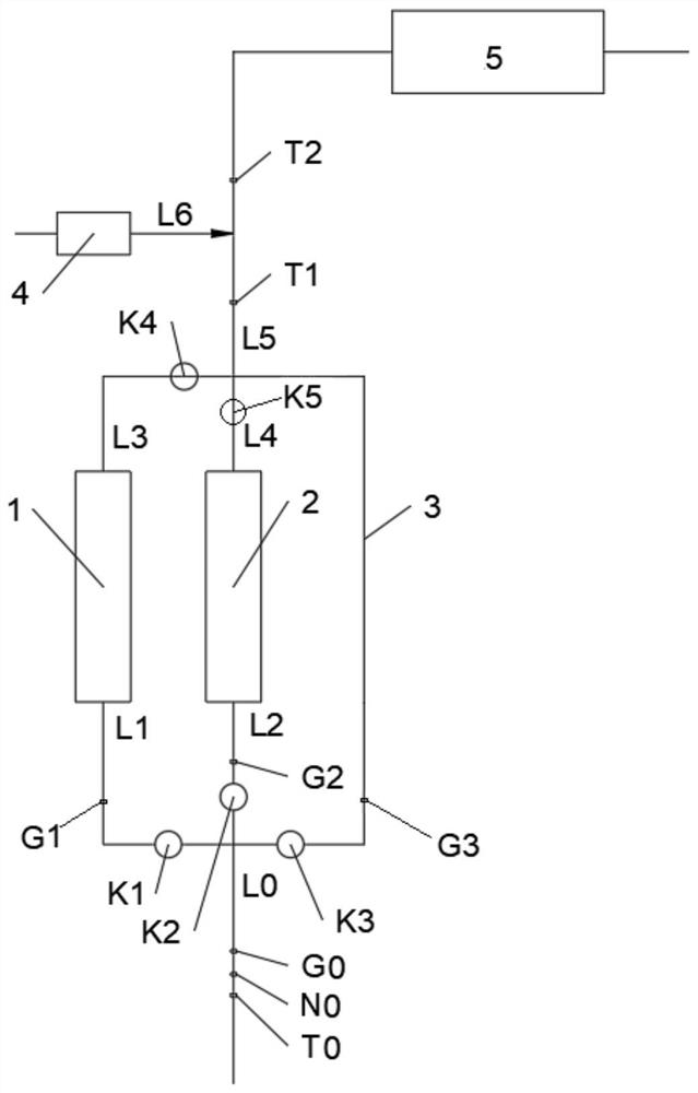
[0103] Such as image 3 As shown, a system for high CO concentration flue gas coupled with low temperature SCR temperature control treatment, the system includes: CO main reaction tower 1, CO adjustment tower 2, bypass flue gas delivery pipeline 3. The total flue gas pipeline L0 with high CO concentration flue gas is divided into three paths: the first pipeline L1 is connected to the CO main reaction tower 1, the second pipeline L2 is connected to the CO regulating tower 2, and the bypass flue gas transmission pipeline 3 is connected. The CO main reaction tower 1 discharges the flue gas after CO catalytic oxidation through the third pipeline L3, and the CO adjustment tower 2 discharges the flue gas after CO catalytic oxidation through the fourth pipeline L4. The ends of the third pipeline L3, the fourth pipeline L4, and the bypass flue gas conveying pipeline 3 are merged into the fifth pipeline L5. The end of the fifth pipe L5 is connected to the SCR reactor 5 .

Embodiment 2

[0105] Embodiment 1 is repeated, except that the first air valve K1 is provided on the first pipeline L1. A second air valve K2 is provided on the second pipeline L2. The bypass flue gas delivery pipe 3 is provided with a third gas valve K3.

Embodiment 3

[0107] Repeat Example 2, except that the device also includes: the original flue gas temperature sensor T0, the original flue gas CO concentration detection sensor N0, the original flue gas flow sensor G0, the first gas flow sensor G1, the second gas flow sensor G2, The third gas flow sensor G3. The raw flue gas temperature sensor T0, the raw flue gas CO concentration detection sensor N0, and the raw flue gas flow sensor G0 are arranged on the main flue gas pipeline L0. The first gas flow sensor G1 is arranged on the first pipeline L1. The second gas flow sensor G2 is disposed on the second pipeline L2. The third gas flow sensor G3 is arranged on the bypass flue gas delivery pipe 3 . The fifth pipeline L5 is provided with a first temperature measuring sensor T1.


PUM


Abstract

The invention provides a high-CO-concentration flue gas coupling low-temperature SCR temperature control method, which comprises the following steps: dividing high-CO-concentration flue gas into threepaths, introducing the first path of flue gas into a main reaction tower for CO catalytic oxidation, introducing the second path of flue gas into an adjusting tower for CO catalytic oxidation, and directly conveying the third path of flue gas through a bypass flue gas conveying pipeline, and controlling the temperature of flue gas entering a SCR reactor within a certain temperature window by regulating and controlling a device and a control system for generating heat by CO conversion. According to the technical scheme, a CO reaction tower catalyst can be replaced or regenerated in a non-stopstate; the temperature rise of the flue gas is controlled by controlling the CO conversion rate, so that the temperature rise caused by CO catalytic oxidation is accurately regulated and controlled; therefore, the temperature of the flue gas entering the SCR reactor is ensured to be in an optimal active reaction temperature window, and the denitration efficiency is further ensured.

Description

technical field [0001] The invention relates to a denitrification and decarbonization method and system, in particular to a denitrification and decarbonization method and system for flue gas with high CO concentration, and belongs to the technical field of flue gas purification. Background technique [0002] For industrial flue gas, especially for sintering machine flue gas in the iron and steel industry, flue gas desulfurization and denitrification technology is a flue gas purification technology applied to the chemical industry where multiple nitrogen oxides and sulfur oxides are generated. Nitrogen oxides and sulfur oxides are one of the main sources of air pollution. Most of flue gas simultaneous desulfurization and denitrification technologies are currently in the research and industrial demonstration stage, but because it can simultaneously achieve desulfurization and denitrification in one system, especially with the X Control standards are becoming increasingly stri...

Claims


Application Information

Patent Timeline
IPC IPC(8): B01D53/86B01D53/75B01D53/62B01D53/56F23J15/08
CPCB01D53/864B01D53/8628B01D53/8631B01D53/75F23J15/08B01D2258/0283Y02A50/20
Inventor 魏进超康建刚李俊杰彭杰
Owner ZHONGYE-CHANGTIAN INT ENG CO LTD
Why Eureka
Try Eureka