
Single-tower desulfurization device and process for low-sulfur coal gas based on complex iron catalyst

A desulfurization device and desulfurization process technology, applied in the field of desulfurization, can solve the problems of poor desulfurization effect, difficulty, large fluctuations in gas hydrogen sulfide content, etc., and achieve the effects of high selectivity, cost reduction, and low operating costs

Inactive Publication Date: 2021-02-26
WUHAN GLT ENERGY & ENVIRONMENTAL TECH CO LTD
View PDF5 Cites 3 Cited by
  • Summary
  • Abstract
  • Description
  • Claims
  • Application Information

AI Technical Summary

Problems solved by technology

In recent years, the hydrogen sulfide content of coal gas used as raw material gas after pre-desulfurization is required to be no more than 20mg / Nm 3 , and when the hydrogen sulfide content in the gas exceeds 3g / Nm 3 When using the traditional PDS desulfurization process, even if it is designed as a two-stage series desulfurization, it is difficult to ensure that the hydrogen sulfide content in the gas after pre-desulfurization is less than 50mg / Nm 3 ; and with the operation of the device, due to the characteristics of the PDS catalyst itself, if the desulfurization liquid is not regularly discharged in large quantities, the secondary salt content of the desulfurization liquid will gradually accumulate, the desulfurization effect will become worse and worse, and the hydrogen sulfide content of the gas after pre-desulfurization Large fluctuations

Method used


Image

  • Single-tower desulfurization device and process for low-sulfur coal gas based on complex iron catalyst
  • Single-tower desulfurization device and process for low-sulfur coal gas based on complex iron catalyst
  • Single-tower desulfurization device and process for low-sulfur coal gas based on complex iron catalyst

Examples


Embodiment Construction

[0028] In order to better understand the present invention, the invention will be described in detail below in conjunction with specific examples.

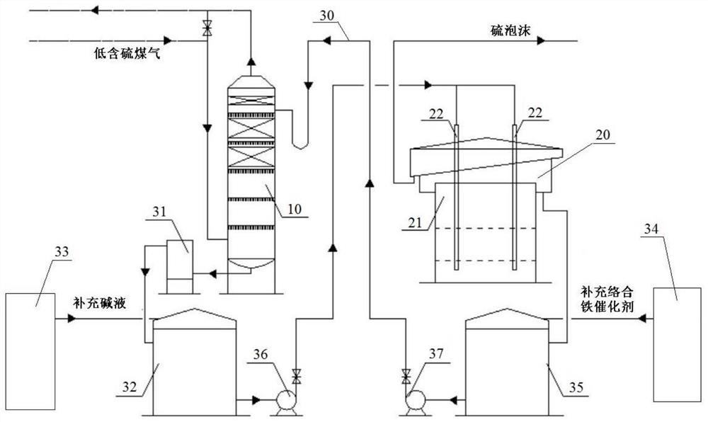
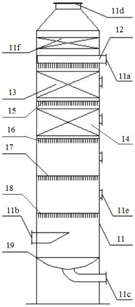
[0029] see figure 1 and figure 2The single-tower desulfurization device for low-sulfur gas based on a complex iron catalyst includes a desulfurization unit, a regeneration unit 20 and a desulfurization liquid circulation unit 30, the desulfurization unit includes a desulfurization tower 10, and the desulfurization tower 10 includes a tower body 11 , the upper part of the tower body 11 is provided with a desulfurization liquid inlet 11a, the lower part of the tower body 11 is provided with a head 19, the top of the head 19 is provided with a gas inlet 11b, and the bottom of the head 19 is provided with a desulfurization liquid outlet 11c , the top of the tower body 11 is provided with a purified gas outlet 11d, the upper part of the tower body 11 is provided with a spray device 12, and the tower body 11 is provided with two layer...


PUM


Abstract

The invention relates to the technical field of desulfurization, in particular to a single-tower desulfurization device and process for low-sulfur coal gas based on a complex iron catalyst. The single-tower desulfurization device for low-sulfur coal gas based on a complex iron catalyst comprises a desulfurization unit, a regeneration unit and a desulfurization liquid circulation unit. The desulfurization unit comprises a desulfurization tower, the desulfurization tower comprises a tower body, a spraying device is arranged at the upper part in the tower body, two packing layers and four layersof liquid distributors are further arranged in the tower body, the four layers of liquid distributors are arranged between a coal gas inlet and the spraying device at equal intervals from top to bottom, a first packing layer is arranged between the spraying device and a first liquid distributor, and a second packing layer is arranged between the first liquid distributor and a second liquid distributor. The desulfurization tower comprises two packing sections and two air spraying sections, and the two packing desulfurization sections and the two spraying desulfurization sections are combined, so that the desulfurization efficiency can be improved, and the hydrogen sulfide content of the low-sulfur coal gas is reduced to 5mg / Nm<3> or below.

Description

technical field [0001] The invention relates to the technical field of desulfurization, in particular to a single-tower desulfurization device and process for low-sulfur gas based on a complex iron catalyst. Background technique [0002] Coal accounts for a large proportion of my country's resource structure, and gas transformed from coal is an important basic chemical raw material. Generally speaking, the hydrogen sulfide content in the gas is directly proportional to the sulfur content of the raw coal processed. For low-sulfur gas, such as semi-water gas, water gas and some coke oven gas, the hydrogen sulfide content in the gas is basically Will not exceed 5g / Nm 3 . The raw gas used in the chemical industry must be desulfurized before use, generally wet pre-desulfurization plus dry fine desulfurization, so as not to cause deactivation of the back-end catalyst. [0003] Gas pre-desulfurization is generally carried out with Na 2 CO 3 Or ammonia is the alkali source, and...

Claims


Application Information

Patent Timeline
Patent Type & Authority Applications(China)
IPC IPC(8): C10K1/08C10K1/00
CPCC10K1/004C10K1/08
Inventor 徐勋达霍保芝王来发谭洪金王东李尽胡璐潘威吴宏观余国贤
Owner WUHAN GLT ENERGY & ENVIRONMENTAL TECH CO LTD
Learn More