
Soil gas collecting device and method

A soil gas and collection device technology, applied in the field of soil gas research, can solve the problems of less gas, loose soil, high soil properties, etc., and achieve the effect of ensuring comprehensive waterproofing, sufficient extraction volume, and wide application range

Pending Publication Date: 2021-02-26
农环科技(上海)有限公司
View PDF0 Cites 0 Cited by
  • Summary
  • Abstract
  • Description
  • Claims
  • Application Information

AI Technical Summary

Problems solved by technology

The static box method is mostly used in the study of greenhouse gas emissions. An opaque box with a known volume is placed on the surface of the earth and enriched for a certain period of time to analyze the gas flux per unit time and unit area. However, this method cannot collect and Studying Soil Gas at Different Depths
The probe method refers to inserting a hollow probe with a conical drill bit (with a stainless steel filter) into the soil at a certain depth, and connecting a syringe, a gas collection bag or a gas collection pump to extract the gas. The requirements are high, and it is difficult to insert the probe in the extremely hard soil. Hitting with a hammer will cause the soil to loosen and cause the bottom filter to be blocked. Wet soil will also cause the bottom filter to be blocked, and the liquid cannot be filtered, resulting in a small amount of gas , easy to extract liquid

Method used

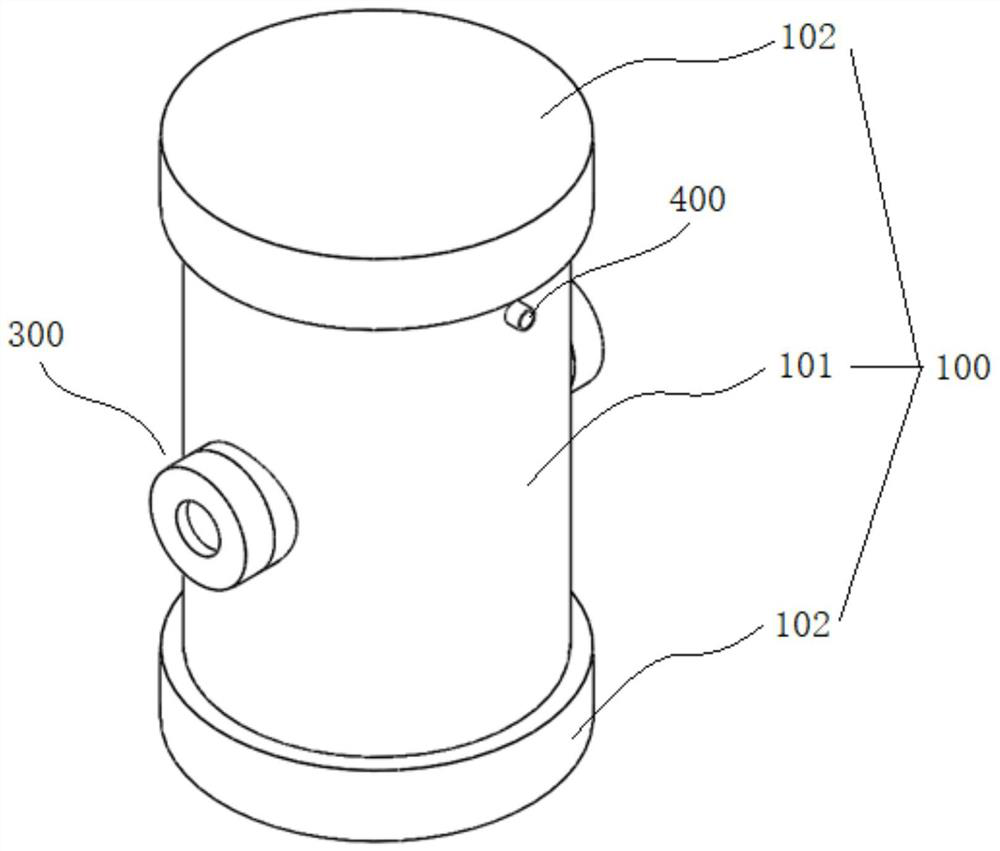
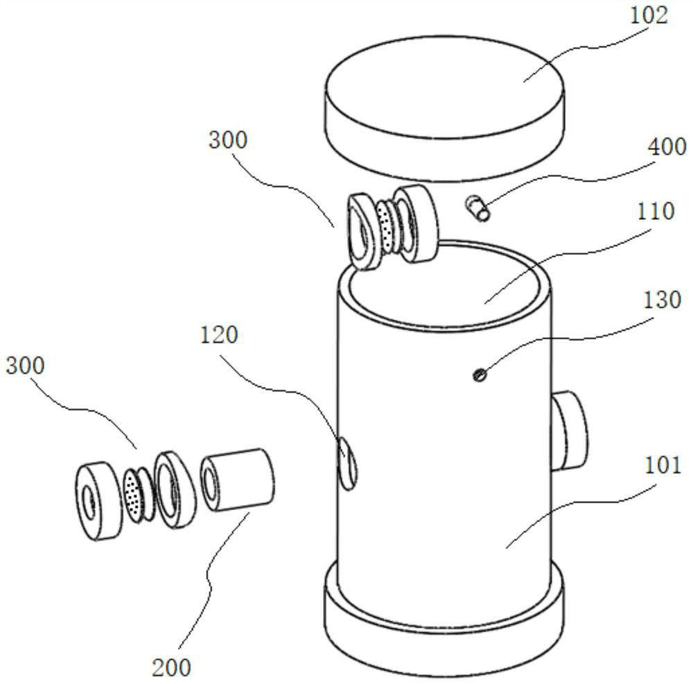
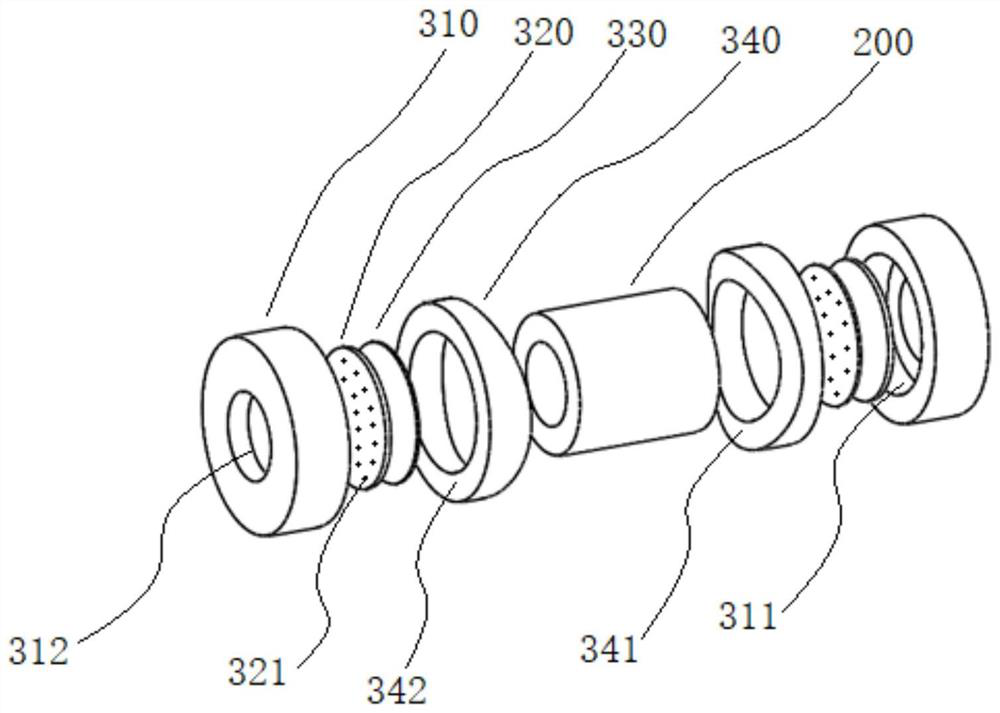

Image

  • Soil gas collecting device and method
  • Soil gas collecting device and method
  • Soil gas collecting device and method

Examples


Embodiment 1

[0074] Such as Figure 4 As shown, the collection cylinder 100 has a built-in gas analyzer 3 (recorder), which analyzes and records soil gas in real time.

[0075] For example, the CO 2 and / or O 2 Turn on the portable gas analyzer 3, set the recording time interval, put it into the collection tube 100, if there is an air extraction channel 130, close the air extraction channel 130, and then vertically bury it in the soil 2, the soil gas will be as preset time, analyze and record soil gas components and concentrations.

Embodiment 2

[0077] Such as Figure 5 As shown, soil gas is collected at different locations at the same depth.

[0078] Taking the soil remediation site as an example, the soil gas collection device 1 is buried in the soil 2 at the same depth at different locations, respectively connected to the exhaust pipe, and the air is taken to the laboratory for further analysis after sampling. This method provides timely insight into whether repair agents such as oxidizers are under-dosed or unevenly dosed.

Embodiment 3

[0080] Such as Figure 6 As shown, soil gas is collected at different depths at the same site.

[0081] Taking the study of soil carbon emission as an example, the soil temperature and soil microbial population at different depths will be different, which in turn affects carbon emission (soil 2 respiration). After the soil gas collection devices 1 are superimposed one by one, they are vertically buried in the soil 2 at different depths at the same site, connected with extraction pipes respectively, and soil gas at different depths are extracted respectively, and brought into the laboratory for further analysis.


PUM


Abstract

The invention discloses a soil gas collecting device and method. The device comprises a collecting cylinder, a connecting pipe and a ventilation assembly. A gas containing cavity is formed in the collecting cylinder and provided with at least one ventilation channel communicated with the outside. The connecting pipe is arranged in the ventilation channel in a penetrating mode. The ventilation assembly comprises a fixing ring cap used for being connected with the connecting pipe, a waterproof ventilation membrane and a supporting piece, the fixing ring cap comprises a large opening end and a small opening end opposite to the large opening end, the large opening end is communicated with the small opening end, the fixing ring cap is detachably connected with one end of the connecting pipe through the large opening end, and the supporting piece is provided with a plurality of through holes. The waterproof breathable membrane and the supporting piece are arranged between the fixing ring capand the connecting pipe after being attached and are attached to one end of the connecting pipe through the small opening end. The device can be directly buried in soil through the collecting cylinder, soil gas of different depths is collected, the device is suitable for different types of soil through pre-burying, and the application range is wide.

Description

technical field [0001] The invention relates to the technical field of soil gas research, in particular to a soil gas collection device and a collection method. Background technique [0002] The gas in the soil is mainly O 2 , CO 2 、CH 4 , SO 2 、H 2 S, NH 3 , N 2 O, H 2 、H 2 O, Rn, etc. These gases are composed of various complex biochemical processes (mineralization, litter decomposition, soil respiration, anaerobic bacterial decomposition, release of organic fertilizer or chemical fertilizer, etc.) and atmospheric deposition (polluted gases are absorbed by the surface after deposition) , and then diffuse into the soil layer) and other processes. In soil remediation, plant physiology research, greenhouse gas emission research, ore prospecting (CO 2 、CH 4 , SO 2 、H 2 S and Hg and other gas chemical prospecting), plant nutrition detection, earthquake prediction (measurement of H in soil 2 Abnormal) and soil radon gas detection before building design (National St...

Claims


Application Information

Patent Timeline
IPC IPC(8): G01N1/22G01N1/26G01N1/24G01N33/00
CPCG01N1/2294G01N1/24G01N1/26G01N33/0009
Inventor 李玉占
Owner 农环科技(上海)有限公司
Learn More