
A New Drilling Method Shaft Tunneling Machine

A technology of drilling method and roadheader, which is applied in the field of new type drilling method shaft roadheader, can solve problems such as unsuitable control of verticality, too long drill pipe, cutterhead, tool drill pipe damage, etc., so as to improve the rock breaking ability of the cutterhead and Efficiency, improved stability and pressure, and the effect of precise drilling construction

Active Publication Date: 2022-04-19
CHINA RAILWAY ENGINEERING EQUIPMENT GROUP CO LTD
View PDF4 Cites 0 Cited by
  • Summary
  • Abstract
  • Description
  • Claims
  • Application Information

AI Technical Summary

Problems solved by technology

However, the equipment still has the following problems, which seriously restrict the popularization and application of the equipment, mainly including: 1. The drill pipe is too long and flexible, which limits the improvement of the torque of the cutterhead; 2. The cutterhead has no stabilizing device and is prone to deflection , causing damage to the cutter head, cutter, drill pipe, etc.; 3. Using gravity guidance, drilling is prone to problems such as deflection and reaming; 4. Problems such as collapsed holes, buried drills, and falling objects during drilling are difficult 5. The construction efficiency in hard rock formation is low; 6. The verticality of the sinking well wall is not suitable to be controlled, and the filling quality of the wall thickness is not easy to control.
[0003] At present, the patent application number is "CN201410106744.1" and the patent name is "New Drilling Method Shaft Drilling Rig", which discloses a drilling method shaft drilling rig that improves drilling efficiency. In the process, the drill pipe is still used to transmit the torque, the transmission torque is small, and the construction energy consumption is large

Method used


Image

  • A New Drilling Method Shaft Tunneling Machine
  • A New Drilling Method Shaft Tunneling Machine
  • A New Drilling Method Shaft Tunneling Machine

Examples


Embodiment 2

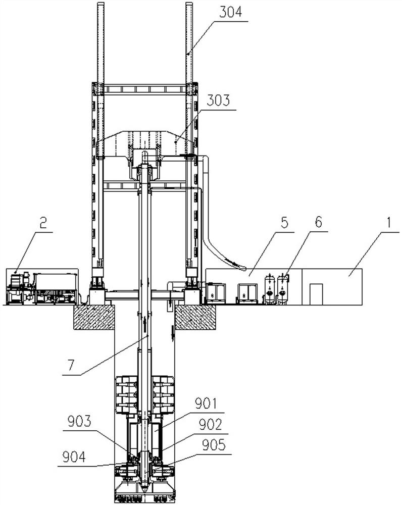
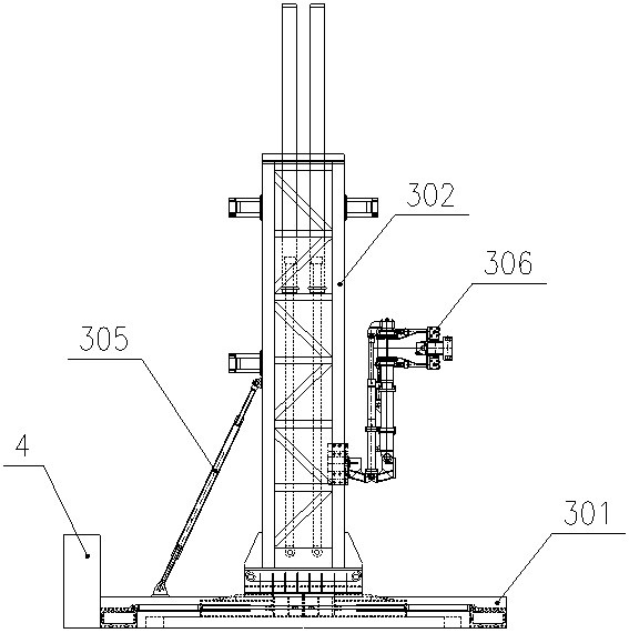
[0040] Embodiment 2: as figure 2 As shown, a new type of drilling method shaft boring machine, the side of the main column 303 is fixed with a drill pipe assembling manipulator 306, the drill pipe assembling manipulator 306 is used for assembling the drill pipe, improves the automation of the drill pipe assembling, and reduces the labor force strength, shortening the working time; the foundation chassis 301 is flexibly connected with the main column 302 through the column tilting cylinder 305, and when the equipment goes out of the well, the main column 302 can be tilted at a certain angle under the action of the column tilting cylinder 305, so that Out of the wellhead, it is convenient for hoisting equipment to lift.

[0041] All the other structures are the same as in Example 1.

Embodiment 3

[0042] Embodiment 3: as Figure 4 As shown, a new type of shaft boring machine with drilling method, the upper part of the fixed slide box 801-3 is fixed with a cutter beam, and the cutter beam is sleeved on the drill pipe 7; Cutter 801-4, several cutters are set in parallel on the cutter beam, use the cutters to solve the problem that the equipment cannot be raised in the well due to the convergence of the soft soil layer during the construction process, when this situation occurs, the cutter can be used to cut and converge the wellbore, Make the equipment go up well smoothly.

[0043] All the other structures are the same as in Example 1.


PUM


Abstract

The present invention proposes a new type of shaft boring machine for well drilling, which includes a derrick and a hydraulic pump station. The upper part of the derrick is provided with a lifting mechanism, which is connected with a sliding frame, which is slidably arranged on the derrick; The moving frame is sequentially connected to the tensioning mechanism and the propulsion mechanism through the drill rod, the tensioning mechanism is connected to the propulsion mechanism, the propulsion mechanism is respectively connected to the stabilizer and the cutter head, and the stabilizer is matched with the cutter head; the hydraulic pump station They are respectively connected with the lifting mechanism, the propulsion mechanism and the stabilizer. The invention introduces the construction concept of tunnel boring machine into the shaft construction, adopts the power submerged drive, there is no counterweight in the well, the drill pipe does not need to transmit torque, and only bears the gravity load, so as to realize the ultra-deep drilling construction, the drive system, the shoe propulsion system, and the stability All structures such as the cutter head are placed underground to directly drive the cutter head to break rock, the support shoe provides the tension force, and the propulsion cylinder provides the propulsion force, improving the rock breaking ability and efficiency of the cutter head and realizing efficient and precise drilling construction.

Description

technical field [0001] The invention relates to the technical field of drilling and boring machines, in particular to a novel shaft boring machine for well drilling. Background technique [0002] The traditional shaft drilling rig adopts top drive, drill pipe transmission, gas lift reverse circulation slag removal, and decompression drilling construction. The top drive adopts full hydraulic drive to drive the drill pipe, the stabilizer stabilizes the drill pipe, drives the bottom cutterhead for excavation, and the spherical tooth hob for rock breaking. Using low-penetration and high-speed drilling method, the rock mass is broken into small pieces of slag, and the mud water circulation is generated by the gas lift method, and the slag is carried to the ground by the high-speed circulating mud water, and then passed through the sedimentation tank, separation station, etc. , separate the rock slag from the mud water, and the mud water enters the recirculation to complete the r...

Claims


Application Information

Patent Timeline
Patent Type & Authority Patents(China)
IPC IPC(8): E21D1/06E21B7/04E21B15/04E21B19/00E21B3/02E21B17/10E21B10/42
CPCE21D1/06E21B7/04E21B15/04E21B19/00E21B3/02E21B17/1078E21B10/42
Inventor 贾连辉肖威贺飞杨聚辉吕旦周倩赵飞闫扬义冯琳袁征范磊龚廷民吴彦星薛广记蒋鹏鹏刘娇
Owner CHINA RAILWAY ENGINEERING EQUIPMENT GROUP CO LTD
Learn More