Automatic wire feeding mechanism for additive manufacturing

A wire feeding mechanism and additive manufacturing technology, applied in manufacturing tools, additive processing, electron beam welding equipment, etc., can solve the problems of low forming efficiency, pollution of processed parts, and increasing the number of times of degassing and exhausting of the vacuum system. Easy to replace effect

Inactive Publication Date: 2021-03-09
翼戈(温州)鞋业有限公司
View PDF7 Cites 2 Cited by
  • Summary
  • Abstract
  • Description
  • Claims
  • Application Information

AI Technical Summary

Problems solved by technology

[0002] There are currently two methods of electron beam additive manufacturing: electron beam fusion powder technology and electron beam fuse forming technology. Electron beam fusion powder technology uses metal powder as raw material, which is difficult to manufacture the required metal powder, high in use cost, and difficult to form. Low efficiency and other disadvantages, electron beam fuse forming can ensure the quality of printed parts to reach the forging level while achieving high-efficiency deposition forming. This technology has the characteristics of no reflection, fast forming speed, high material utilization rate, and high energy conversion efficiency. Now In the prior art, the wire feeding system provides raw material supply for the electron beam fuse rapid prototyping equipment. At present, the wire feeding mechanism used in the electron beam fuse device is set in the vacuum chamber, that is, the wire feeding mechanism and the fuse deposition part are in the same place. In the vacuum chamber, the electron beam fuse forming equipment is characterized by a fast deposition rate of the fuse, and the deposition rate is as high as 15kg / h. Taking the ordinary 20kg wire as an example, the melting time is only a few hours, so frequent wire replacement is required. During the material process, the vacuum system must be closed and the vacuum chamber door must be opened, so the number of vacuum system degassing and pumping is increased. At the same time, in order to prevent high-temperature oxidation of the printed parts, it is necessary to cool the metal printed parts to room temperature in a vacuum environment, thereby prolonging the printing time. In addition, frequent opening of the vacuum chamber door may cause problems such as contamination of the workpiece, especially during the working process, repeated heating and cooling increases the internal stress of the printed piece. If the wire feeding mechanism is placed outside the vacuum chamber, due to the The pipeline is connected to the atmospheric environment, so the wire feeding process will inevitably bring the gas into the vacuum chamber through the wire feeding pipeline, resulting in insufficient vacuum in the vacuum chamber and affecting the quality of the electron beam spot and printing quality

Method used


Image

  • Automatic wire feeding mechanism for additive manufacturing
  • Automatic wire feeding mechanism for additive manufacturing
  • Automatic wire feeding mechanism for additive manufacturing

Examples


Embodiment Construction

[0033] The following will clearly and completely describe the technical solutions in the embodiments of the present invention with reference to the accompanying drawings in the embodiments of the present invention. Obviously, the described embodiments are only some, not all, embodiments of the present invention. Based on the embodiments of the present invention, all other embodiments obtained by persons of ordinary skill in the art without making creative efforts belong to the protection scope of the present invention.

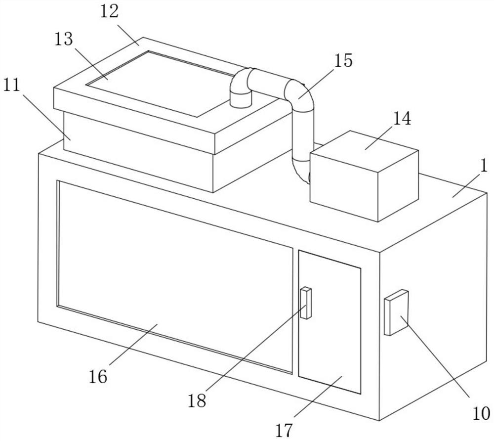
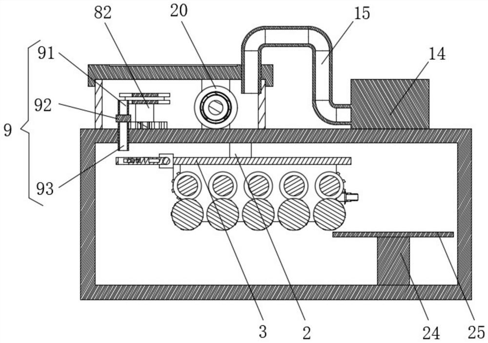
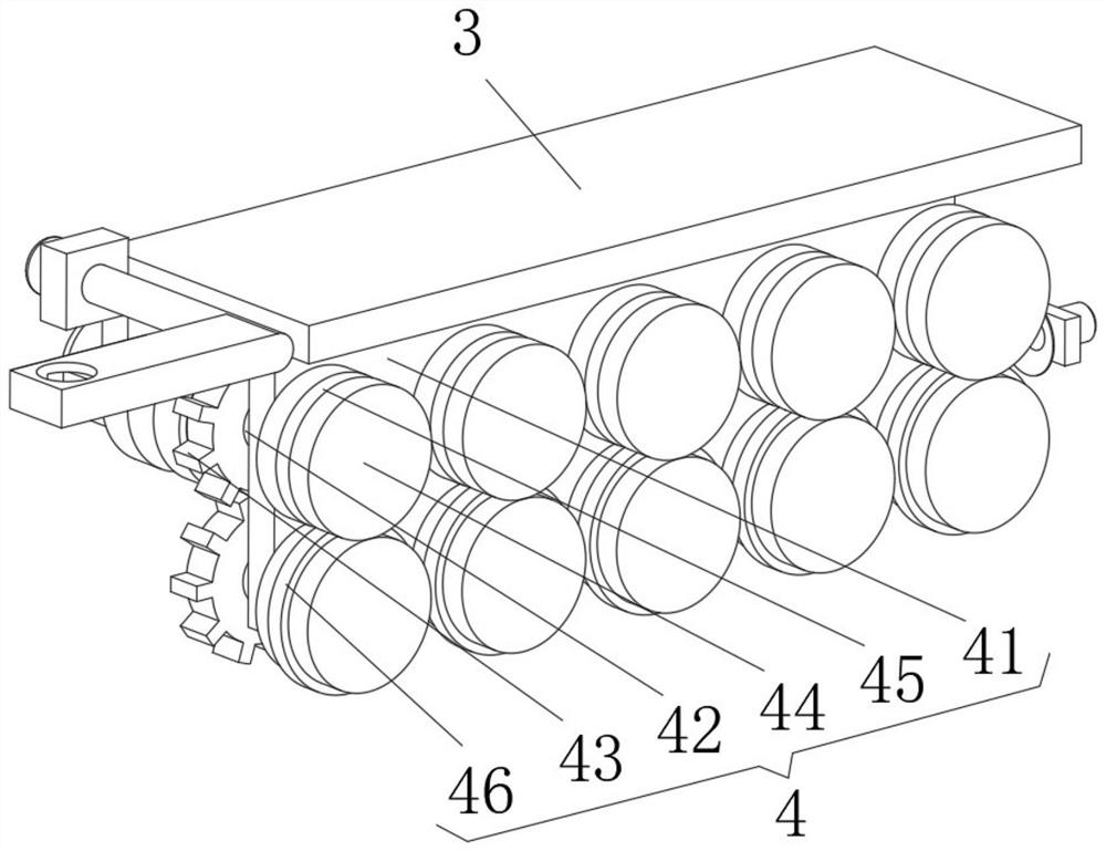
[0034] see Figure 1-7 , the present invention provides a technical solution: an automatic wire feeding mechanism for additive manufacturing, including a vacuum box 1, a wire feeding assembly 4, a rotating assembly 5, a connecting assembly 6, a wire drawing assembly 7, a conveying assembly 8 and a guiding assembly 9;

[0035] Vacuum box 1: a connecting block 2 is fixed on the inner upper side wall, and a connecting plate 3 is fixed on the lower side of the con...


PUM


Abstract

The invention discloses an automatic wire feeding mechanism for additive manufacturing. The automatic wire feeding mechanism comprises a vacuum box, a wire feeding assembly, a rotating assembly, a connecting assembly, a wire drawing assembly, a conveying assembly and a guiding assembly; a connecting block is fixed to the upper side wall of the interior of the vacuum box, and a connecting plate isfixed to the lower side surface of the connecting block; the wire feeding assembly comprises a mounting plate, rotating shafts, first gear rings, connecting discs, a first annular groove and an extrusion ring, the mounting plate is fixed to the lower side surface of the connecting plate, connecting through grooves which are evenly distributed are formed in the front side surface of the mounting plate, the rotating shafts are rotationally connected inside the connecting through grooves, the first gear rings are fixed to the back ends of the circumferential surfaces of the rotating shafts, eachfirst gear ring on the upper side meshes with the first gear ring on the lower side, and the connecting discs are fixed to the front end surfaces of the rotating shafts. wire feeding and wire changingcan be conducted conveniently, and air can be prevented from entering a vacuum chamber.

Description

technical field [0001] The invention relates to the technical field of wire feeding mechanisms, in particular to an automatic wire feeding mechanism for additive manufacturing. Background technique [0002] There are currently two methods of electron beam additive manufacturing: electron beam fusion powder technology and electron beam fuse forming technology. Electron beam fusion powder technology uses metal powder as raw material, which is difficult to manufacture the required metal powder, high in use cost, and difficult to form. Low efficiency and other disadvantages, electron beam fuse forming can ensure the quality of printed parts to reach the forging level while achieving high-efficiency deposition forming. This technology has the characteristics of no reflection, fast forming speed, high material utilization rate, and high energy conversion efficiency. Now In the prior art, the wire feeding system provides raw material supply for the electron beam fuse rapid prototyp...

Claims


Application Information

Patent Timeline
Patent Type & Authority Applications(China)
IPC IPC(8): B23K15/00B33Y30/00
CPCB23K15/00B33Y30/00
Inventor 李秋波
Owner 翼戈(温州)鞋业有限公司
Why Eureka
Try Eureka