Treatment mechanism of engine cylinder
A technology for engine cylinders and heat treatment equipment, which is applied in the direction of heat treatment furnaces, heat treatment equipment, and process efficiency improvement, can solve problems such as low production efficiency, poor coherence, and split production steps, and achieve improved structural strength, ensure cleanliness, Avoid effects that affect production
- Summary
- Abstract
- Description
- Claims
- Application Information
AI Technical Summary
Problems solved by technology
Method used
Image
Examples
Embodiment 1
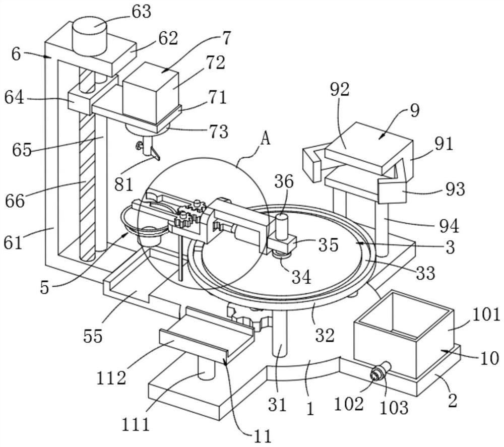
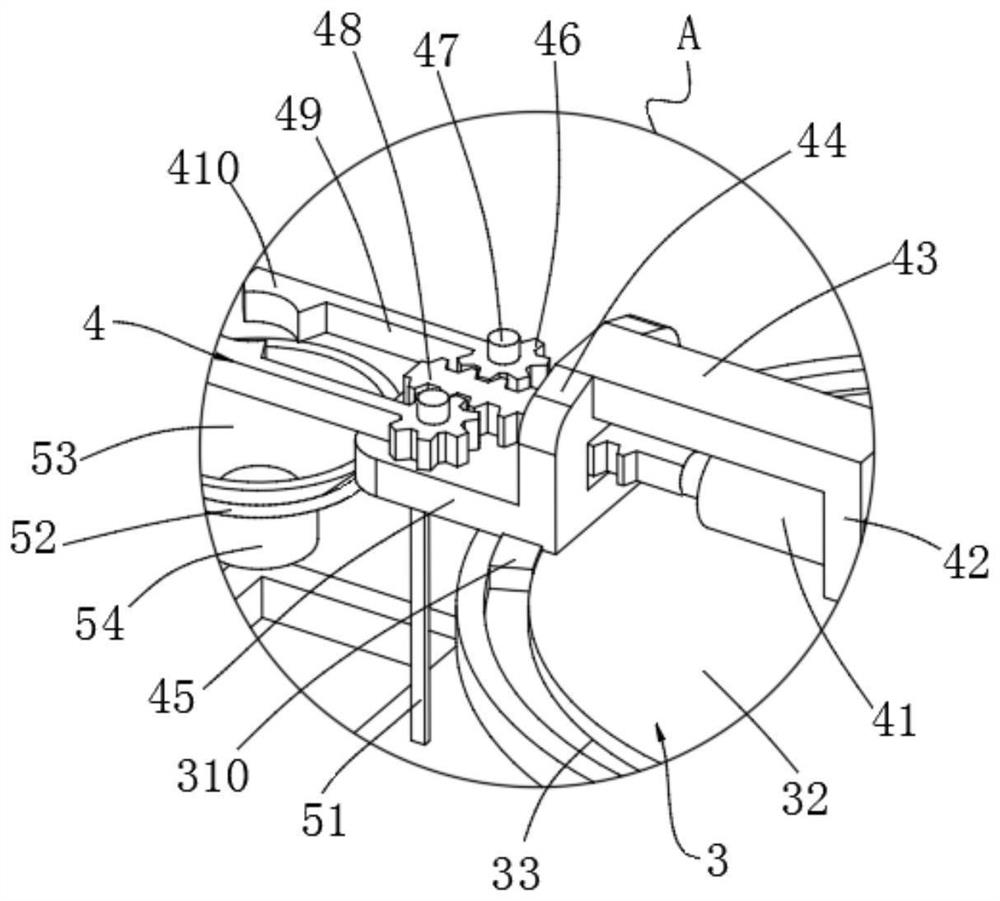
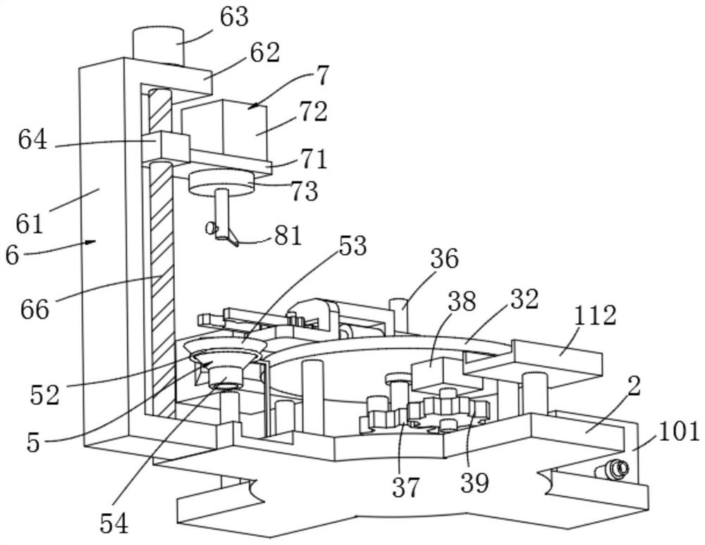
[0044] Example 1, please refer to Figure 1-7 , this embodiment provides a technical solution: a processing mechanism for an engine cylinder, including a chassis 1, an angle adjustment unit 3, a clamping unit 4, a height adjustment unit 6, a boring power unit 7, and an adjustable boring knife unit 8 and heat treatment unit 9;
[0045] The top of the chassis 1 is installed with the clamping unit 4 through the angle adjustment unit 3, and the side of the chassis 1 is provided with four mounting plates 2 at equal angles. An adjustable boring knife unit 8 is installed on the bottom of the power unit 7, and a heat treatment unit 9 is installed on the rear mounting plate 2; for example, "left side" and "rear side" are relative to the reader's perspective.
[0046] The heat treatment unit 9 includes a heat treatment equipment box 91, a baffle plate 92, an L-shaped door panel 93, an equipment box leg 94, an electric push rod 95, a strut 96, an end rod 97, a through hole 98, a door pa...
Embodiment 2
[0060] Example 2, please refer to Figure 1-2 , this embodiment provides a technical solution: a processing mechanism for an engine cylinder, the difference is that it also includes a debris collection unit 5, and the debris collection unit 5 includes a strut 51, a fixed collar 52, a conical Collecting cover 53, downpipe 54 and groove 55, on the mounting plate 2 on the left side, offer the groove 55 that is used to place collecting barrel, on the mounting plate 2 on the left side, also be fixed with fixed collar 52 by pole 51, fix A conical collection cover 53 is sleeved inside the collar 52 , and a downpipe 54 is connected to the bottom of the conical collection cover 53 .
[0061] The debris produced during the boring process goes out with the lower side of the engine cylinder, and then is collected by the conical collection cover 53, and slides down through the downpipe 54 to the collection bucket placed in the groove 55, which can facilitate the collection of debris genera...
Embodiment 3
[0062] Embodiment three, please refer to figure 1 , the present embodiment provides a technical solution: a treatment mechanism for an engine cylinder, the difference is that it also includes a quenching unit 10, the quenching unit 10 includes a quenching box 101, a water pipe 102 and a water valve 103, and the installation on the right side A quenching box 101 is arranged on the plate 2, and a water pipe 102 is connected to the bottom side of the quenching box 101, and a water valve 103 is installed on the water pipe 102.
[0063] The quenching treatment of the engine cylinder can be completed through the quenching unit 10, and the structural strength of the engine cylinder can be improved. The water pipe 102 and the water valve 103 can complete drainage, which is convenient for replacing the quenching water.
[0064] In other embodiments, it also includes a placement unit 11, the placement unit 11 includes a placement leg 111 and a placement plate 112, the mounting plate 2 o...
PUM
 Abstract
Description
Claims
Application Information
 - R&D
- Intellectual Property
- Life Sciences
- Materials
- Tech Scout
- Unparalleled Data Quality
- Higher Quality Content
- 60% Fewer Hallucinations
Browse by: Latest US Patents, China's latest patents, Technical Efficacy Thesaurus, Application Domain, Technology Topic, Popular Technical Reports.
© 2025 PatSnap. All rights reserved.Legal|Privacy policy|Modern Slavery Act Transparency Statement|Sitemap|About US| Contact US: help@patsnap.com


